Download
1 / 16
160 likes | 281 Views
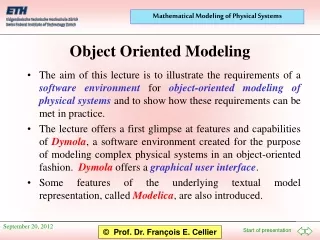
The aim of this lecture is to illustrate the requirements of a software environment for object-oriented modeling of physical systems and to show how these requirements can be met in practice.

E N D
The aim of this lecture is to illustrate the requirements of a software environment for object-oriented modeling of physical systems and to show how these requirements can be met in practice. The lecture offers a first glimpse at features and capabilities of Dymola, a software environment created for the purpose of modeling complex physical systems in an object-oriented fashion. Dymola offers a graphical user interface. Some features of the underlying textual model representation, called Modelica, are also introduced. Object Oriented Modeling
The causality of the model equations Graphical modeling Model structure in Modelica Model topology in Modelica Inheritance rules Hierarchical modeling Table of Contents
i + U0 = f(t) i = U0 / R Different Equations - - R R Identical Objects I 0 I 0 I0 = f(t) u = R· I0 The causality of the equations must not be predetermined. It can only be decided upon after the analysis of the system topology. U 0 The Causality of the Model Equations
Physical objects should be representable by mathematical graphical objects. The graphical objects should be topologically connectable. The mathematical models should be hierarchically describable. To this end, it must be possible to represent networks of coupled objects again as graphical objects. Basic Requirements of OO Modeling
An Example model Circuit1 SineVoltage U0(V=10, freqHz=2500); Resistor R1(R=100); Resistor R2(R=20); Capacitor C(C=1E-6); Inductor L(L=0.0015); Ground Ground; equation connect(U0.p, R1.p); connect(R1.n, C.p); connect(R2.p, R1.n); connect(U0.n, C.n); connect(Ground.p, C.n); connect(L.p, R1.p); connect(L1.n, Ground.p); connect(R2.n, L.n); end Circuit1; Dymola Modelica
Graphical Information (Annotation) package CircuitLib annotation (Coordsys( extent=[0, 0; 504, 364], grid=[2, 2], component=[20, 20]));model Circuit1 annotation (Coordsys( extent=[-100, -100; 100, 100], grid=[2, 2], component=[20, 20]));Modelica.Electrical.Analog.Sources.SineVoltage U0(V=10, freqHz=2500) annotation (extent=[-80, -20; -40, 20], rotation=-90);Modelica.Electrical.Analog.Basic.Resistor R1(R=100) annotation (extent=[ -40, 20; 0, 60], rotation=-90);Modelica.Electrical.Analog.Basic.Capacitor C(C=1E-6) annotation (extent=[-40, -60; 0, -20], rotation=-90);Modelica.Electrical.Analog.Basic.Resistor R2(R=20) annotation (extent=[0, -20; 40, 20]);Modelica.Electrical.Analog.Basic.Inductor L(L=0.0015) annotation (extent=[40, 20; 80, 60], rotation=-90);Modelica.Electrical.Analog.Basic.Ground Ground annotation (extent=[0, -100; 40, -60]);equationconnect(U0.p, R1.p) annotation (points=[-60, 20; -60, 60; -20, 60], style(color=3));connect(R1.n, C.p) annotation (points=[-20, 20; -20, -20], style(color=3));connect(R2.p, R1.n) annotation (points=[0, 0; -20, 0; -20, 20], style(color=3));connect(U0.n, C.n) annotation (points=[-60, -20; -60, -60; -20, -60], style(color=3));connect(Ground.p, C.n) annotation (points=[20, -60; -20, -60], style(color=3));connect(L.p, R1.p) annotation (points=[60, 60; -20, 60], style(color=3));connect(L.n, Ground.p) annotation (points=[60, 20; 60, -60; 20, -60], style(color=3));connect(R2.n, L.n) annotation (points=[40, 0; 60, 0; 60, 20], style(color=3));end Circuit1;end CircuitLib;
Models in Modelica consist of a descriptionof theirmodel structure as well as a description of their embedding in the model environment: Models in Modelica model Model name Description of the model embedding; equation Description of the model structure; end Model name;
The model structure in Modelica consists either of a set of equations, a description of the model topology, or a combination of the two types of model structure descriptions. A topological model description is usually done by dragging and dropping model icons from graphical model libraries into the modeling window. These models are then graphically interconnected among each other. The stored textual version of the topological model consists of a declaration of its sub-models (model embedding), a declaration of its connections (model structure), as well as a declaration of the graphical description elements (annotation). Model Structure in Modelica
Instance name Class name Modifier Connection Connector Model Topology in Modelica model MotorDrive PI controller; Motor motor; Gearbox gearbox(n=100); Shaft Jl(J=10); Tachometer wl; equation connect(controller.out, motor.inp); connect(motor.flange , gearbox.a); connect(gearbox.b , Jl.a); connect(Jl.b , wl.a); connect(wl.w , controller.inp); end MotorDrive;
Voltage R i v v u p n connector Pin Voltage v; flow Current i; end Pin; type ElectricPotential = Real (final quantity="ElectricPotential", final unit="V"); type Voltage = ElectricPotential; Resistors in Modelica model Resistor "Ideal resistor" Pin p, n; Voltage u; parameter Resistance R; equation u = p.v - n.v; p.i + n.i = 0; R*p.i = u; end Resistor;
R i C i v u v v u v p n n p Similarity Between Different Elements model Resistor "Ideal resistor" Pin p, n; Voltage u; parameter Resistance R; equation u = p.v - n.v; p.i + n.i = 0; R*p.i = u; end Resistor; model Capacitor "Ideal capacitor" Pin p, n; Voltage u; parameter Capacitance C; equation u = p.v - n.v; p.i + n.i = 0; C*der(u) = p.i; end Capacitor;
partial model OnePort Pin p, n; Voltage u; equation u = p.v - n.v; p.i + n.i = 0; end OnePort; model Resistor "Ideal resistor" extends OnePort; parameter Resistance R; equation R*p.i = u; end Resistor; model Capacitor "Ideal capacitor" extends OnePort; parameter Capacitance C; equation C*der(u) = p.i; end Capacitor; i v u v u u v v v v R i i p p n p n n C Partial Models and Inheritance
Courtesy Toyota Tecno-Service Decomposition and Abstraction
Simulation and Animation Modeling Window Animation Window
Brück, D., H. Elmqvist, H. Olsson, and S.E. Mattsson (2002), “Dymola for Multi-Engineering Modeling and Simulation,” Proc. 2nd International Modelica Conference, pp. 55:1-8. Otter, M. and H. Elmqvist (2001), “Modelica: Language, Libraries, Tools, Workshop, and EU-Project RealSim,” Modelica web-site. References