Download
1 / 11
110 likes | 169 Views
A Software Service Routine describing the Atlas Inner Detector Materials. Steve Armstrong, Christian Hansen and Rikard Sandstr ö m November 2002, Uppsala This talk can be found at http://chansen.home.cern.ch/chansen/WORK/talks.html. Introduction - LHC.

E N D
A Software Service Routine describing the Atlas Inner Detector Materials Steve Armstrong, Christian Hansen and Rikard Sandström November 2002, Uppsala This talk can be found at http://chansen.home.cern.ch/chansen/WORK/talks.html Christian Hansen, CERN
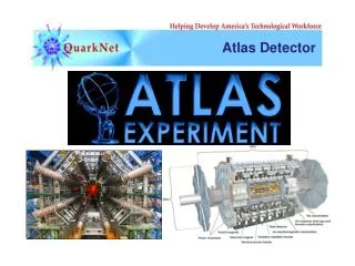
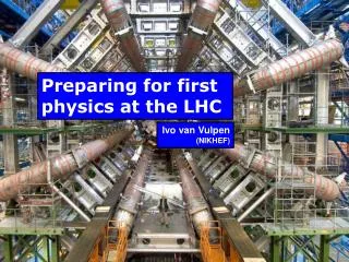
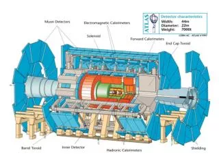
Introduction - LHC The Large Hadron Collider (LHC) at CERN ATLAS, A Toroidal LHC ApparatuS Christian Hansen, CERN
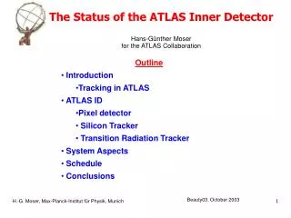
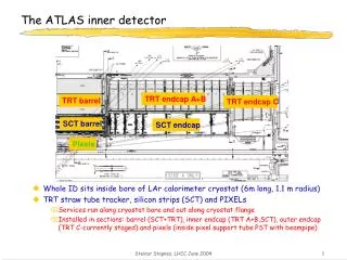
Introduction – Inner Tracker Measures the directions, momenta, and charge of particles produced in each proton-proton collision • Consists of three different systems • Pixel Detectors • Silicon Strip Detectors, SCT • Transition Radiation Tracker, TRT • All in a solenoidal magnetic field parallel to the beam axis Christian Hansen, CERN
Introduction – Reconstruction 10 azimuthal positions from Pixel and Strip detectors (r < 50 cm) 36 azimuthal positions from TRT (50 cm < r < 100 cm) These signals are sorted into patterns produced by helical trajectories Then directions, momenta and charge for the particles are determined It is needed to select 1 interesting event out of 10 million background events The particle tracks can be distorted by the material of the detector For more accurate reconstruction the information about the material in the detector will be provided to the reconstruction packages by the Material Integration Service (MIS) Christian Hansen, CERN
Introduction - MIS Material Information for ID is presently hard coded differently in various Reconstruction Packages Our goal is to provide a service reading from GEANT ID descriptions Christian Hansen, CERN
Use of GEANT Example of a parameter set • User defined number of Geantinos sent out spherically (TRTSimG4, Zalite) 26. Production of a GeantinoMap: #179 < ProduceGeantinoMap = 1 > #180 < NbrOfGeantinoStepsInPhi = 10 > #181 < PhiMax = 90 > #182 < PhiMin = 0 > #183 < NbrOfGeantinoStepsInEta = 10 > #184 < EtaMax = 2.5 > #185 < EtaMin = 0. > • Geantinos take new StepPoint for each new material element encountered • For each StepPoint, RadiationLength is given from GEANT4 Christian Hansen, CERN
VolumeElement Vs. GeantinoStep Approach VolumeElement (VE) Approach: GeantinoStep (GS) Approach: • ID is segmented into cylindrical VolumeElements (VE) • Each VE has an average RadiationLength ( X0 ) • User specified line between x1 and x2 intersects VEs and the x/X0 is determined • Suitable for fine spaced structures • In TRT used for wires, gas, straws, radiator and twistor • Geantinos take a new step for each new material • Each GS are saved with its RadiationLength ( X0 ) • The line between x1 and x2 has GS projected on to it and x/X0 is determined • Suitable for disjoint structures • in TRT used for support, module, SCTService and cooling Christian Hansen, CERN
MIS – VolumeElement Approach • Each VE gets its average RadiationLength (X0j) from intersecting geantinos • Each VE gets the length that the line between x1 andx2 is intersecting it (xj) • The xj / X0j, for each intersected VE are summed together Christian Hansen, CERN
MIS – The Geantino Step Approach • For large structures (like support) the GeantinoSteps and X0 are saved • GeantinoSteps are projected on to line between x1 andx2 Works in 3D!!! • RadiationLengthFraction between x1 andx2 is sum of ProjectionSteps (xi /X0i ) Christian Hansen, CERN
PRELIMINARY!!! RadiationLengthFraction (x/X0)for TRT Step Approach An attempt to reproduce G4 values by the use of Step Approach and VolumeElement Approach Disagreement since the methods are under development VolumeElement Approach Christian Hansen, CERN
MIS G4 G3 Muon Release Future Plans • Pixels: Working with Davide Costanzo’s G4Pixel • SCT: Plan to work with Andrea Dell’Acqua’s G4Sct • Continue to validate results (converting to G4) • Benchmark speed / optimize performance • Continuing to encounter substantial challenges using ATLSIM(Hope to continue work with Fred Luehring (TRT) and Pavel Nevski) • Have had nice discussions with Ada Farilla and Armin Nairz • Have given status tutorial of MIS to Armin • Difficult to assign dates – work preliminary • May not be possible to include in Release 5.0.0 • Everything in /afs/cern.ch/c/chansen/PUBLIC/ Draft to ATLAS note is being prepared and available : /afs/cern.ch/user/c/chansen/PUBLIC/MATERIALINTEGRATIONSERVICE/DOCUMENT/mis.tex Christian Hansen, CERN