Download
1 / 31
310 likes | 472 Views
Remote Alarm Reporting and Site Monitoring Equipment. 16810, Avenue of Fountains, Suite # 108, Fountain Hills, AZ 85268, U.S.A. Phone : +1 (480) 816-8672 Fax : +1 (480) 816-0115 E-mail : sales@oriontelecom.com Web Site: http://www.oriontelecom.com. Updated : January 1st, 2005. Slide 1.

E N D
Remote Alarm Reporting and Site Monitoring Equipment 16810, Avenue of Fountains, Suite # 108, Fountain Hills, AZ 85268, U.S.A. Phone: +1 (480) 816-8672 Fax: +1 (480) 816-0115 E-mail: sales@oriontelecom.com Web Site: http://www.oriontelecom.com Updated : January 1st, 2005 Slide 1
Remote Alarm Suite Product Overview Remote Alarm Reporting, Site Monitoring and Management Equipment Suiteoffer three types of solutions Remote Alarm Reporting - Solution # 1 Remote Site Monitoring - Solution # 2 Line Testing - Solution # 3 Slide 2
Remote Alarm Suite Remote Alarm Reporting, Site Monitoring and Management Equipment Suite- An Overview • Used to configure, monitor, control and manage remote sites from a central monitoring location over • Dedicated serial data (RS232) links, • Over the Internet (TCP/IP protocol). Slide 3
Remote Alarm Suite Remote Site Alarm Input Terminal • Access, manage and control Remote Site Alarms • Alarms Reporting. • Manage through PC using a Window based GUI • Can be accessed, managed and controlled from a Central Site over : • a) Serial RS232 Data Link • b) The Internet (using TCP/IP Protocol) Central Site Alarm Recording Equipment • Store and (continuously) log ALL Alarms that, may appear at the Remote • Sites during any given 7 days & 24 hour time period. • Can configure the Remote Site equipment using a Windows based GUI Slide 4
Remote Alarm Suite Uses and Applications • SCADA applications power distribution lines, oil pipe lines, • gas pipelines and water pipe lines. • Monitoring and Managing Remote (unmanned) Cellular Sites. • Managing and Monitoring Remote Radio Relay (unmanned) Sites. • Managing and Monitoring Remote DLC or RSU (unmanned) • telecom sites. • Security and Surveillance. Slide 5
Remote Alarm Suite Remote Alarm Reporting, Site Monitoring and Management Equipment Suite offers the following alarms and functions • Remote Site Alarms • Equipment Alarm(s) Relay Open / Relay Close (User • Configurable) Up to 32 Alarm Inputs per Site / Location. • Intruder Alarm • Fire Alarm • Smoke Alarm • Flooding Alarm. • AC Mains Power Failure Alarm, etc. Slide 6
Remote Alarm Suite • Remote Site Monitoring Facility • To Monitor following parameters • Remote Site Temperature • AC Mains Voltage at the Remote Site • DC Battery Voltage of the battery-bank of the power backup • equipment (12VDC and 48VDC). • Remote Site Control Facility • Management of the power back-up battery banks • Read voltage remotely • Set threshold limit to shut-down / switch over to another • source - AC main or Solar Slide 7
Remote Alarm Suite • Temperature Monitoring and Management facility • “Monitor and Read” temperature of each remote sites • Site environmental management • automatically "switch-on" or "switch-off" vent fans / • heaters / air conditioners at the high / low temperature • thresholds set by the User. • Providing a power "Re-Set” to any equipment - remotely • Initiate and provide a Power-Set (turn-off / turn-on) to any • equipment installed at the Remote Site from a Central • Monitoring location. Slide 8
Remote Alarm Suite • Remote line / cable pair testing - Telecom application • Perform the line testing of the remote cable pairs • Test the line for Open, Short, Leakage and the • presence of "foreign" AC potential on the cable pairs. • Ideal for Telco deployment at hard-to-reach unmanned • Remote Sites • Helps to isolate the faulty cable pair before making a • service call Slide 9
Remote Alarm Suite Solution # 1: Remote Site Terminal: • Connect up to 32 Relay Inputs • Powered by -48 VDC input (AC main optional) • “Relay Open” or “Relay Close” condition to generate • an “Alarm” - User Configurable • Used to monitor, control and manage remote sites from a • central monitoring location over • a) Dedicated Serial data (RS232) links • b) Over the Internet (TCP/IP protocol). Slide 10
Remote Alarm Suite Central Site Equipment • Report and recognize upto 32 Alarm Inputs at each Remote Site • Store and (continuously) log ALL Alarms that, may appear • at the Remote Sites during any given 7 days & 24 hour • time period. • Configure using a Window based GUI • Display the status of all the Active Alarm on LCD display • Can be connected upto 8 Remote Sites Slide 11
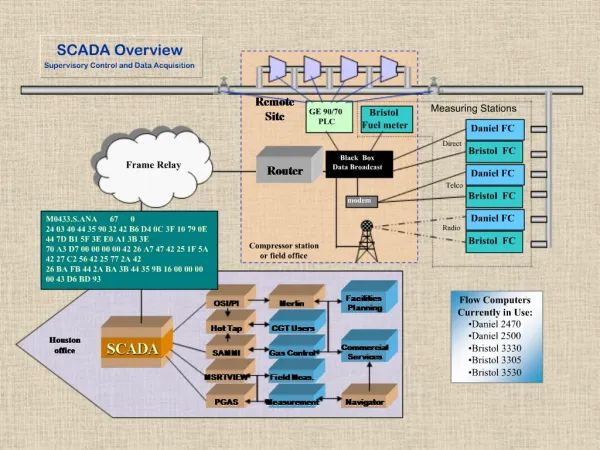
Remote Alarm Suite Dedicated serial data (RS-232) links VCL-Monitoring System Dedicated Serial (Asynchronous, RS 232) Links VCL-Remote Device VCL-Remote Device Site 1 Site 5 1 to 32 Relays 1 to 32 Relays VCL-Remote Device VCL-Remote Device Site 2 Site 6 1 to 32 Relays 1 to 32 Relays VCL-Remote Device VCL-Remote Device Site 3 Site 7 1 to 32 Relays 1 to 32 Relays VCL-Remote Device VCL-Remote Device Site 4 Site 8 1 to 32 Relays 1 to 32 Relays (Example: using dedicated serial data (RS-232) links ) Slide 12
Remote Alarm Suite TCP/IP Protocol Networked (Internet) Links Central Office VCL-Monitoring System 10 BaseT Ethernet Networked (TCP/IP Protocol) Remote Network / Site 1 Remote Network / Site 8 INTERNET HUB HUB VCL-Remote Device VCL-Remote Device Networked (TCP/IP Protocol) Networked (TCP/IP Protocol) 32 Relay Inputs 32 Relay Inputs Remote Network(s) 3 through 6 Remote Network / Site 2 Remote Network / Site 7 HUB HUB VCL-Remote Device VCL-Remote Device 32 Relay Inputs 32 Relay Inputs (Example : using TCP/IP protocol networked (Internet) Links) Slide 13
Remote Alarm Suite Mixed network of dedicated serial (RS-232) Data links and network (TCP/IP) protocol links Central Office VCL-Monitoring System Dedicated Serial (Asynchronous, RS 232) Links 10 BaseT Ethernet Remote Network / Site 1 HUB INTERNET Remote Site 8 VCL-Remote Device VCL-Remote Device 32 Relay Inputs 32 Relay Inputs Remote Network(s) 3 through 4 Remote Network / Site 2 Remote Site(s) 6 through 7 HUB Remote Site 5 VCL-Remote Device VCL-Remote Device 32 Relay Inputs 32 Relay Inputs (Example: Using a "mixed" network of dedicated serial (RS-232) Data links and network (TCP/IP) protocol links) Slide 14
Remote Alarm Suite Central site - Alarm Monitoring Equipment (Front View) - 48 V 5V ACK “Scroll” LCD Display Remote Site # Alarm Site # System # (Remote #) Alarm # Text of Alarm (Configured by the user) Alarm Acknowledge Switch Central site - Alarm Monitoring Equipment (Back View) RJ-45 for connection with dedicated serial data (RS-232) links or networked TCP-IP links DB-9 for connection with PC Slide 15
Remote Alarm Suite Central Site Alarm Recording Equipment : Specifications Specifications of RS 232 @ 9.6Kbps, Asynchronous Data Interface Port for Serial (Point to Point) Connection : to connect upto 8 remote sites to the central monitoring site on point to point serial data links. Number of Remote Site (Remote Terminals) That can be Connected to central site Monitoring Equipment 8 (Remote Terminals) Type RS 232 Tx, Rx, Gnd Mode Asynchronous Baud Rate 9.6 kbps - Fixed Data Size 8bits Parity None Flow Control None ( Xon / Xoff ) Stop Bit 1 Slide 16
Remote Alarm Suite Ethernet Specifications @ 10 BaseT Data Interface Port for Networked (IP/Internet) Connection : to connect upto 8 remote sites to the central monitoring site over networked (IP/Internet) links. Number of Remote Site (Remote Terminals) That can be Connected to central site Monitoring Equipment 8 (Remote Terminals) Conformity IEEE 802.3. Type 4 Wire,Twisted Pair Cabling. (Categories 3, 4 or 5). Distance limit 100 metres (Approx. 328 feet) per Segment. Bit Rate 10 Mbps. Power: -48VDC (AC Input Optional) Dimensions: 2U High 19-inch Shelf (19-inch rack mounting). Slide 17
Remote Alarm Suite Specifications of RS 232 @ 9.6Kbps, Asynchronous Data Interface Port for Serial (Point to Point) Connection : to connect upto 8 remote sites to the central monitoring site on point to point serial data links. Number of Relay Inputs (User Configurable - Relay Open Relay Close Alarm Inputs) Per Remote Site Terminal 32 Connection between Remote Site Terminal and Central Site Terminal Serial Data Interfaces 1 Type RS 232 Tx, Rx, Gnd Mode Asynchronous Baud Rate 9.6 kbps - Fixed Data Size 8bits Parity None Flow Control None ( Xon / Xoff ) Stop Bit 1. Slide 18
Remote Alarm Suite Ethernet Specifications @ 10 BaseT Data Interface Port for Networked (IP / Internet) Connection : to connect upto 8 remote sites to the central monitoring site over networked (IP/Internet) links. Connection between remote site terminal and central site terminal Ethernet Interfaces 1 Conformity IEEE 802.3. Type 4 Wire, Twisted Pair Cabling. (Categories 3, 4 or 5). Distance limit 100 metres (Approx 328 feet) per Segment. Bit Rate 10Mbps Power: -48VDC (AC Input Optional) Dimensions: 1U High 19-inch Shelf (19-inch rack mounting). Slide 19
Remote Alarm Suite Remote site - Alarm Input Terminal RJ-45 for connection with ethernet 32 Relay Inputs ("Relay Open", or "Relay Close" condition to generate an "Alarm" -User Configurable). DB-9 for connection with dedicated serial data (RS-232) links Slide 20
Remote Alarm Suite Solution # 2 Remote Site Monitoring Equipment • Remote Site Management & Monitoring can be connected • to Central Site through • a) Dedicated Serial (RS232) data link • b) Internet TCP/IP Protocol • Any number of Remote Site Monitoring equipment may be • installed and managed from Central Site. • All Remote Site Monitoring, Management and Control • function are accomplished through a PC using a Window • based GUI. Slide 21
Remote Alarm Suite Control and Manage the following functions Provide the following Alarms: • Intruder Alarm • Fire Alarm • Smoke Alarm • Flooding Alarm. • Equipment Alarm(s) Relay Open / Relay Close (User • Configurable) Upto 5 Alarm Inputs per Site / Location. • AC Mains Power Failure Alarm. • And to select the “switch” to the selected back-up • power source. • “Read" and "Control" Remote Site Temperature • Temperature monitoring and management facility Slide 22
Remote Alarm Suite • "Read" AC Mains Voltage at the Remote Site. • “Read" DC Battery Voltage of the battery-bank • of the power back-up equipment (12VDC and 48VDC) • and "Manage" "battery-banks. • Remotely read the voltage of power and back-up battery • Set the threshold limit to shut down or to switch over to • another battery line “remotely” • Useful in case where there is two power back-up units for • added protection • To initiate a Power "Re-Set" of the connected Equipment. • To provide a power reset to any equipment - remotely Slide 23
Remote Alarm Suite Dedicated serial data (RS-232) links Central Office Dedicated Serial (Asynchronous, RS 232) Links VCL-Remote Device Site 8 1 to 32 Relays (Example: using dedicated serial data (RS-232) links ) Slide 24
Remote Alarm Suite TCP/IP protocol networked (Internet) Links Central Office 10 BaseT Ethernet Remote Network / Site 8 Remote Network / Site 1 INTERNET HUB HUB VCL-Remote Device VCL-Remote Device 32 Relay Inputs 32 Relay Inputs Networked (TCP/IP Protocol) Networked (TCP/IP Protocol) Remote Network(s) 3 through 6 Remote Network / Site 2 Remote Network / Site 7 HUB HUB VCL-Remote Device VCL-Remote Device 32 Relay Inputs 32 Relay Inputs (Example : using TCP/IP protocol networked (Internet) Links) Slide 25
Remote Alarm Suite Mixed network of dedicated serial (RS-232) Data links and network (TCP/IP) protocol links Central Office Dedicated Serial (Asynchronous, RS 232) Links COM 1 COM 2 10 BaseT Ethernet Remote Network / Site 1 Remote Site 8 VCL-Remote Device HUB INTERNET 32 Relay Inputs VCL-Remote Device Remote Network(s) 2 through 7 Remote Network / Site 8 32 Relay Inputs HUB VCL-Remote Device 32 Relay Inputs (Example: Using a "mixed" network of dedicated serial (RS-232) Data links and network (TCP/IP) protocol links) Slide 26
Remote Alarm Suite Specifications of RS 232 @ 9.6Kbps, Asynchronous Data Interface Port for Serial (Point to Point) Connection : to connect upto 8 remote sites to the central monitoring site on point to point serial data links. Number of relay inputs (user configurable - relay open relay close alarm inputs) Per Remote Site Terminal 32 Connection between Remote Site Terminal and Central Site Terminal Serial Data Interfaces 1 Type RS 232 Tx, Rx, Gnd Mode Asynchronous Baud Rate 9.6 kbps - Fixed Data Size 8bits Parity None Flow Control None ( Xon / Xoff ) Stop Bit 1 Slide 27
Remote Alarm Suite Ethernet Specifications @ 10 BaseT Data Interface Port for Networked (IP/Internet) Connection : to connect upto 8 remote sites to the central monitoring site over networked (IP/Internet) links. Connection between remote site terminal and central site terminal Ethernet Interfaces 1. Conformity IEEE 802.3. Type 4 Wire, Twisted Pair Cabling. (Categories 3, 4 or 5). Distance limit 100 metres (Approx 328 feet) per Segment. Bit Rate 10 Mbps. Slide 28
Remote Alarm Suite Solution # 3 • Remote line / cable pair testing - Telecom application • Perform the line testing of the remote cable pairs • Test the line for Open, Short, Leakage and the • presence of "foreign" AC potential on the cable pairs. • Ideal for Telco deployment at hard-to-reach unmanned • Remote Sites • Helps to isolate the faulty cable pair before making a • service call Slide 29
Remote Alarm Suite Orion’s Products • E1, Voice & Data Drop-Insert Multiplexer • PRI ISDN (Q.931) Multiplexers • E1 Intelligent Channel Banks • E1 / T1 DCME (Digital Circuit Multiplication Equipment) - Voice Compression Equipment • Thin Route DCME • E1 / T1 Echo Cancellers • E1 / T1 Digital Cross Connect • T1 / E1 Converters • E3, 34Mbps Multiplexer • 34Mbps Optical Line Transmission Equipment (OLTE) • STM 1 / STM 4 - SDH Equipment • Remote Asset Management Systems Slide 30
Remote Alarm Suite Thank you for your attention For more details visit us at our Web Site at http://www.oriontelecom.com 16810, Avenue of Fountains, Suite # 108, Fountain Hills, AZ 85268, U.S.A. Phone: +1 (480) 816-8672 Fax: +1 (480) 816-0115 E-mail: sales@oriontelecom.com Slide 31