Download
1 / 4
40 likes | 236 Views
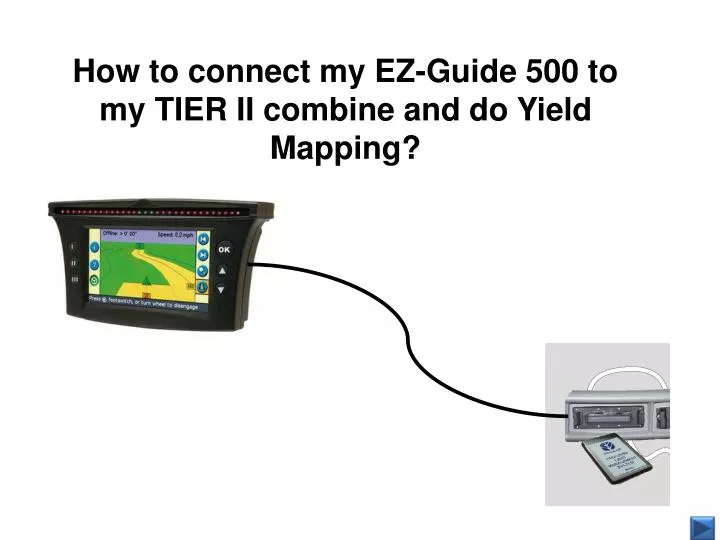
How to connect my EZ-Guide 500 to my TIER II combine and do Yield Mapping?. Connecting the EZ-Guide 500 to the Data Logger Unit for GPS mapping. Connect the EZ-Guide 500 to the Data Logger Unit for GPS mapping: TIER II combines

E N D
How to connect my EZ-Guide 500 to my TIER II combine and do Yield Mapping?
Connecting the EZ-Guide 500 to the Data Logger Unit for GPS mapping • Connect the EZ-Guide 500 to the Data Logger Unit for GPS mapping: TIER II combines • The EZ-Guide 500 can be connected to the Data Logger Unit to provide GPS data for yield mapping. After logging the data, it is possible to produce maps with the desktop software. • Use the following cables to connect the EZ-Guide 500 to the Data Logger Unit: • female/female standard (straight-through) 9-pin gender adapter (source locally) • 87302445 - 9-pin to 5-pin adapter • 87363745 - 5-pin to 8-pin adapter • Note: The 9-pin gender adapter must be installed between the EZ-Guide 500 lightbar and the 87302445 cable. • Configure the lightbar to output data in the following format: • Data type: NMEA • Data bits: 8 • Parity: None (N) • Stop bits: 1 • Baud rate: 4800bps • Hertz rate: 1hz • NMEA Strings: GGA and VTG turned ON, all others turned OFF
How to connect my EZ-Guide 500 to my AFS600/Intelliview II Plus monitor
Connecting the EZ-Guide 500 to the AFS 600/ Intelliview II Plus display • The color touch screen display features a 9-pin (DE9) serial connector. This connector is located on the bottom of the display,. In display software versions prior to 16, the serial connector is disabled and is not used for any purpose. In display software versions 16 and higher, the serial connector can be used to input a GPS signal into the AFS600/ Intelliview II Plus display.To use the serial connector for GPS input, follow the steps below: • Configure the receiver to output data in the following format: • Data type: NMEA • Data bits: 8 • Parity: None (N) • Stop bits: 1 • Baud rate: 4800bps - 38,400bps (the color display works best with most receivers at 38,400bps) • Hertz rate: 1hz or 5hz • NMEA Strings: GGA and VTG turned ON, all others turned OFF • 2. Connect the EZ-Guide 500 to the display serial connector using a 9-pin data cable (87297613) . The EZ-Guide 500 must be powered separately, as the 9-pin serial connection cannot supply power to the receiver.) • 3. Most devices require an additional ground to be able to transmit NMEA strings through the serial connector on the color display. The recommended method is to build a jumper harness where the ground (pin 5) of the serial port is connects to the ground wire (pin 14) on the 26-pin connector. • 4. Power up the display and go to MAIN > TOOLBOX > GPS. • 5. Set the GPS Connection Type to 'RS232B‘. The display is now configured to accept the signal from the EZ-Guide 500 through the 9-pin serial connector. If the receiver does not communicate with the display immediately, cycle power to the display and receiver. You can view the GPS signal status on the MAIN > DIAGNOSTICS > GPS screen.