Download
1 / 19
190 likes | 194 Views
This review discusses the machine protection and closed orbit requirements for the LHC, including aperture limits, interlocking systems, and fast position interlock. The importance of maintaining tight tolerances for orbit and aperture stability is emphasized. The review also covers the role of orbit feedback systems in stabilizing the beam and preventing failures.

E N D
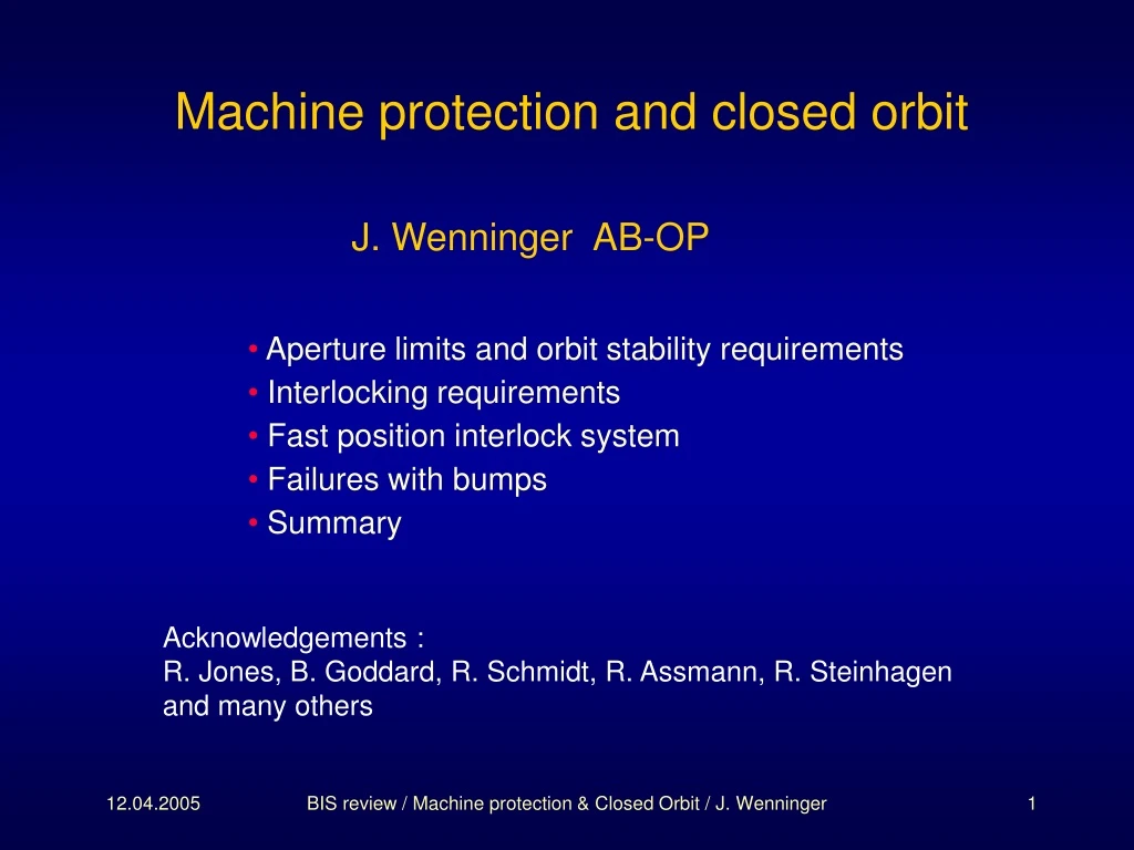
Machine protection and closed orbit J. Wenninger AB-OP • Aperture limits and orbit stability requirements • Interlocking requirements • Fast position interlock system • Failures with bumps • Summary Acknowledgements : R. Jones, B. Goddard, R. Schmidt, R. Assmann, R. Steinhagen and many others BIS review / Machine protection & Closed Orbit / J. Wenninger
Machine apertures at injection Mech. aperture of LHC ring defines the scale aring 8s tight aperture Protection devices protect ring aperture aprot < aring protect against injected beam Secondary collimators tighter than protection asec < aprot limit the amount of halo hitting protection devices Primary collimators tighter than secondary aprim 5-6s < asec primary collimators define the aperture bottleneck in the LHC for cleaning of the circulating beam! • These conditions must always be fulfilled : orbit tolerances are at the level of 0.1-0.5s 100-500 mm. ! long distance correlations : some objects are separated by kms ! • The aperture definition includes tolerances for beta-beat (20%), orbit (4 mm), energy offsets, spurious dispersion… BIS review / Machine protection & Closed Orbit / J. Wenninger
Machine aperture at 7 TeV Settings at 7 TeV for fully squeezed beams (b* = 0.5 m IR1/5) Low-beta triplet aperture defines the scale atriplet 9s Protection devices must protect aperture aprot < atriplet protect against asynchronous beam dump Secondary collimators tighter than protection asec < aprot minimize halo hitting protection devices Primary collimators tighter than secondary aprim 5-6s < asec primary collimators define the aperture! • Operation at nominal intensity requires excellent beam cleaning. orbit tolerance around collimators is in the range s/3 ~ 70 mm. BIS review / Machine protection & Closed Orbit / J. Wenninger
To dump block 8σ 4σ 7σ aperture Q4 Q4 MKD TCDQ TCDS 7σ aperture ± 4mm 450 GeV D D D S S S M M M 8σ aperture 8σ aperture Beam dump region : orbit tolerances Courtesy R. Jones • Dump channel protection : orbit excursion must be smaller than ±4 mm. Prevent damage to extraction channel • Protection against asynchronous dump : orbit excursion < 0.5-2s at TCDQ absorber downstream of the beam dump (depends on energy, b*…) Limit number of bunches escaping to collimators and other machine elements. BIS review / Machine protection & Closed Orbit / J. Wenninger
Orbit stabilization For nominal performance the orbit tolerances are very tight. The relative position of collimators, absorbers.. must be maintained. The orbit is not a ‘play-parameter’ for operation, except at low intensity. ‘Playing’ with the orbit will result in quasi-immediate quench at high intensity. At the LHC the orbit must always be very well controlled, but perturbations during various phases (snapback, ramp, squeeze) can be large and fast. Stabilization by a real-time orbit feedback system Stabilization of both beams around the rings Maintain orbit at critical collimators, absorbers and aperture limits Long distance correlations are important ! Operation of the FB limits the operational freedom of operators BIS review / Machine protection & Closed Orbit / J. Wenninger
Orbit feedback Some FB system details : • Fully digital feedback. • Centralized control with high performance (multi-processor) PCs. • System involves over 100 VME front-end crates. Data is collected from ~ 70 BPM crates central control fan out to PC crates. • Max. operation frequency is estimated to be ~ 25 Hz. • Algorithms will aim to minimize impact of faulty BPMs wrong steering. Optimization of correction performance versus robustness. A proto-type system (using the LHC BPM acquisition system) has been operated very successfully at the SPS, albeit with only … 6 BPMs (1000 at the LHC). This FB system : plays a critical role to maintain relative alignments of protection elements. is not able to counteract orbit changes due to the most critical powering failures. is not a fail-safe system, since it is much too complex. Not part of MP system. BIS review / Machine protection & Closed Orbit / J. Wenninger
450 GeV ramp injection at 26 GeV FB proto-type at the SPS Steering example with external noise over one SPS cycle feedback off BPM Reading (m) feedback on Time (milliseconds) feedback on (zoom) ~ measurement noise !!
Fast orbit changes A large number of failures imply: • Fast global orbit drifts, up to 1 mm/ms in some locations (1 ms ~ 10 turns) PC failures… • Fast amplitude growth of oscillations Transverse damper failure or incorrect input, instabilities… Such orbit changes sooner of later lead to beam loss • BLMs at aperture limiting collimators see the loss first. Critical condition: the collimators must really define the aperture ! • BLM reaction time depends on shape of the halo. Halo is sensitive to machine details (non-linearity, beam-beam…) interlock on fast orbit drifts as complement the BLM system. BIS review / Machine protection & Closed Orbit / J. Wenninger
Beam position interlocking To be protected : • Beam dump channel (±4 mm). • Magnets & collimators from asynchronous beam dump. beam position relative to TCDQ absorber needs to be maintained slow drifts software interlock …. • Collimators (and of course all the rest…) from fast orbit changes. redundancy for the BLM system ! Implementation issues : • We cannot HW interlock the entire LHC orbit select ‘strategic’ position • Concentrate on beam dump requirements and fast position changes. • ‘Slow’ (< 1 Hz) orbit ‘drifts’ surveyed by a software interlock system. BIS review / Machine protection & Closed Orbit / J. Wenninger
2 x 130mm diameter stripline BPMs 2 x 80mm diameter stripline BPMs Beam position interlock layout • IR6 (beam dump IR) has now 4 interlock BPMs per beam • 2 redundant BPMs added near TCDQ and 2 near preceding Q4. • 90° phase advance to cover all betatron phases. • large betatron function ~ 600 m sensitivity. • combined protection of dump channel and protection against fast orbit changes. BIS review / Machine protection & Closed Orbit / J. Wenninger
Interlock thresholds : beam dump channel To define effective tolerances we must look at a ‘bad’ case: • Warm D1 separation dipole failure @ 7 TeV gives ~ 60 mm/turn: Response time: 1 turn (detection) + 2 turns (BIC delay & abort gap synchronization) 200 mm movement between detection and dump. • For a single pilot bunch of 5109 protons the BPMs have a single shot (turn) resolution of ~1.5% of half radius: ~ 300 mm for 80 mm diameter BPM (at Q4) ~ 500 mm for 130 mm diameter BPM (at TCDQ) Interlock threshold: Set to4 - 0.2 - 0.5 = 3.3 mmto give an effective threshold of 4mm. • Damper failures @ injection ~ 1s / 4 turns ~ 400 mm / turn. Requires similar threshold if trigger on a few bunches (for nominal bunches). BIS review / Machine protection & Closed Orbit / J. Wenninger
Interlock thresholds : collimator protection Injection (450 GeV) : • Arc mech. aperture at 8s. • TCDQ (asynch. dump protection) sits at 7s & collimators at 5-6s • 4 mm beam position tolerance corresponds to < 2s Protected by 4mm beam position interlock Allows Q-meter kicks at max kicker strength of 1.75s for a centred beam. Provides some margin for injection oscillations. 7 TeV : • Primary collimators sit at 5-6s with respect to the beam. • D1 failure may result in collimator damage after ~3 ms ~ 30 turns. loss of around 1012 protons • Orbit only moves by ~2 mm over 3 ms at interlock BPMs must be sensitive to fast 1 mm changes. BIS review / Machine protection & Closed Orbit / J. Wenninger
Beam position interlock design BDI group implementation proposal : System is based on a modified LHC orbit digital acquisition card • Bunch-by-bunch acquisition system • Direct comparison of positions & thresholds performed inside a FPGA no dependence on external software • Auto-triggered system no dependence on external timing • For fast orbit changes, observe only relative change wrt preceding closed orbit no dependence on external orbit references • Two output signals to beam interlock system 1 signal for the beam dump aperture, 1 signal for fast changes BIS review / Machine protection & Closed Orbit / J. Wenninger
Beam position interlock design issues • Issues : dump channel protection • Spurious triggers, latency How many bunches must be out of limit before dumping? For single or few bunches this will imply an increased latency, but risk is lower • Alignment and position offsets Do we measure these with the beam or reduce the threshold to include them? • Issues : fast orbit changes • Limited to relative orbit changes 1 mm offset wrt stable orbit • Comparison of current position to last orbit Local orbit reference updated every 20ms Can compare single bunch position (for oscillations) & /or 1 turn orbit • Only valid for nominal bunch intensity BPM single bunch resolution < 100mm Some of the issues may be determined by operational experience… BIS review / Machine protection & Closed Orbit / J. Wenninger
Bumps The position interlock can only intercept failures that lead to an orbit change at the beam dump IR, The BPM interlock system does not protect against local bumps We must consider the following situations : • Local orbit bumps with a circulating beam. • Local orbit bumps during injection. BIS review / Machine protection & Closed Orbit / J. Wenninger
Bumps on circulating beam • Bump growth / arcs Max. SpeedMax. amplitudeArc aperture 450 GeV 3s / s ~ 240 s ~ 8 s 7 TeV 0.8s / s ~ 50 s ~ 40 s If the strength margin for orbit correction is taken into account, cannot reach the ARC aperture at 7 TeV. The ramp speed will be limited in practice to ~ ½ the quoted figure (PC control). • BLM sampling times • Arcs : < 2.5 ms ~ 25 turns • Collimators & critical locations : 1 turn BLM system can detect a beam loss due to a bump before damage occurs. . (>)> arc aperture BIS review / Machine protection & Closed Orbit / J. Wenninger
Bumps with injected beam If no beam is circulating must inject a safe beam Principle for safe injection no problem for injection of the safe beam. Boundary conditions for injection of unsafe beam : • Beam must be circulating. A ‘bumped’ beam must be at least 2-3s away from aperture (low int.) For a pilot bunch, this will not lead to a quench. • Injection oscillations are limited to ~ 5s by transfer line collimators. Failure scenario : Loss of ~ 1013 protons at the bump could lead to damage !!! Low intensity beam bumped close to aperture Nominal injection of 3 ×10¹³p with 3s inj. oscillation BIS review / Machine protection & Closed Orbit / J. Wenninger
Protection against a ‘bumped beam failure’ • Survey the orbit and corrector settings at injection by software interlock 1 Hz surveillance should be sufficient Reference obtained from average readings/settings over few days • Freeze orbit during injection, i.e. no changes by operators. But the feedback will be active ! FB algorithm must not produce bumps from false BPM readings • Limit bump amplitude range & speed by control system Limitation on corrector ramp rate Can we implement this fully consistently ? • Enforce rigorous operation procedures Never ‘jump’ to many orders of magnitude in intensity in one step pilot intermediate intensity (few 1012 p) nominal injection (few 1013 p) We have no solution based on HW interlocks, but the measures proposed above could be sufficient. BIS review / Machine protection & Closed Orbit / J. Wenninger
Summary • A fast beam position interlock system at the LHC is foreseen to : • protect the beam dump channel against damage. • protect the LHC against fast global orbit movements. • provide redundant protection with respect to the BLM system. • The technical realization is feasible and the tolerances of this interlock system are acceptable. • Local bumps at injection cannot be detected by this interlock system : • combined failures (large bump + large injection oscillations) can lead to damage. • counter-measures must implemented for such cases : • SW interlocks. • Protection by the control system • Rigorous OP procedures BIS review / Machine protection & Closed Orbit / J. Wenninger