Download

1 / 20
200 likes | 343 Views
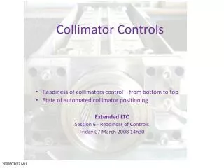
LHC Collimator Survey Train. Concept / Development / Status. Remote Controlled Measurements in the LHC. Patrick Bestmann CERN BE/ABP/SU. IWAA2010 14/09/2010. Overview. Motivation.

E N D
LHC Collimator Survey Train Concept / Development / Status Remote Controlled Measurements in the LHC Patrick Bestmann CERN BE/ABP/SU IWAA2010 14/09/2010
Motivation • Remanent dose rate map between D4 and Q5 after 180 days of continious operation with one month of cooling time
Motivation • Significant activation of material by the beam cleaning process in Point 3 and 7 • High Dose rates for peronnel in Place (4mSv/h) • 500m of Beamline concerned at Point 7 • 26 Quadrupoles and 37 Collimators • Conventionalmeasurements ~90h • Control of the Collimator Alignmentusing a remote controlled system
Task definition • Control of the collimator alignment in vertical and horizontal direction • Relative to the neigbouring quadrupoles • Requested precision 0.2 mm • Respecting the ALARA principle (As Low As Reasonably Achievable)
„TIM“ Train Inspection Monorail • How to bring theequipmentin place? • Train based on themodular TIM concept • Train forvisualinspections • TractionModule • BatteryModule • Sensor Module • Control Module • The trainis controlled either by the user Interface or the measurementprogram
„TIM“ Train Inspection Monorail Tractionunit Sensor unit Controlunit Batteryunit
Concept • Digital closerangephotogrammetry • Fast and non contactmeasurement of theactivatedcollimators • Wireoffsetmeasurementstodetecttrainpositionand link the different aquisitionvolumes. • Reliablestraightreferenceoverlongdistances • Precise model forthewire sag isneeded Collimators Quad Quad
Concept Collimator Quad Quad Targets Wire Sensor Cameras
Concept Targets External lights Wire Reference Pin Inclination sensor
Sensors • AEROEL XLS35-XY laser micrometer as wire measurement system • Open sensor configuration • Large field of view 35mm • Commercial on the market • AICON MoveInspect HR Photogrammetric system • WYLER Zerotronic Inclination Sensors
XLS-35 Micrometer • Optical Laser Micrometer • Measurement of dark/lighttransistions • Relative positionof 2 wirestothereferencepin • 200Hz aquisitionfrequency • Linearityof ±2.5µm • Repeatabilityof ±2µm
Photogrammetric System • Commercial Photogrammetric system AICON MoveInspect HR • 4 AVT Marlin F-201B Cameras in industrial housing • Syncbox • Calibration Panel • MoveInspect HR software • Custom modifications MoveInspectHR
Photogrammetric System • Single shotsynchronisedaquisition • Automatic image measurement andcalculations • We obtain a set of 3D coordinates with identified point groups for collimator andwiresensorsystems • Nosimultaneouscalibration; adjustedintersections
Targets • Retro targets are sensitive to radiation • Use of non retro targets • Production of special aluminium targets • whole body made of black matt aluminium • with light grey aluminium insert
Calculations • 3 different coordiante systems • Left arm with measured wire • Right arm with measured wire • Photogrammetric system with arms and collimator • 7P transformations of the arm systems into the photosystem • Axis alignment to the wire using 3 translations and 2 rotations • Rotation of the y axis (wire axis) using the measured inclination of the two arms
Systems Arm System Camera System
Resultsare 3D coodinatesfor each collimatorandquadrupole in following coordinate system: • Aligned with the inclined wire • Z axis in a vertical plane • Generating LGC++ file • using the x coordinates as horizontal offsets • using the z coordinates as vertical distances (reduced by the slope and the wire sag) • Online LGC++ calculation and comparison with theoretical values
Operation • Autonomoussystem after thestartupprocedure • Startup; Calibration; Sequencedefinition • ControlledbytheLabView Software • Sequencerrunning on thetrain • Remote Panel informingtheoperator
Status • Sensorsystems are running • All Subroutines are running • Tunnelinstallation completed • Finalising Software • Finalising Hardware configuration • Tests.....