Download
1 / 15
150 likes | 265 Views
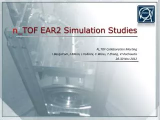
EAR2 Collimator Simulations. Ida Bergstrom Vasilis Vlachoudis 12 Feb 2013. Simulations for the Experimental Area. Preliminary study of Collimator Capture Fission setup EAR-2 Background Neutron dump External wall Shielding for the EAR2 walls and beam dump Study of dose due to skyshine

E N D
EAR2 Collimator Simulations Ida Bergstrom Vasilis Vlachoudis 12 Feb 2013
Simulations for the Experimental Area • Preliminary study of Collimator • Capture • Fission setup • EAR-2 Background • Neutron dump • External wall • Shielding for the EAR2 walls and beam dump • Study of dose due to skyshine • Study of residual dose rate and air activation Neutron Dump External Wall ExperimentalArea 2nd Collimator As shown on last CB meeting
Background in EAR2 (CB meeting status) • Beam profile and background in the area for fission setup (worst case) • WARNING: • 1st and 2nd collimator are not optimized • Beam dump is not optimizedfor back-scattering Non-optimized!4-5 ordersof magnitude As shown on last CB meeting
Background Sources Epithermal • Background: • Thermal & Epithermal: • 50% from collimator • 50% from dump • Fast: • - 100% from collimator • Both are not optimized Factor ×2 Fast
Collimator Profile Borated Poly Iron Beam Profile 4 1 Sample Pb Target Flux 2 3 Radius Direct – Full View Contributes to the Plateau/Flat Direct – Partial View Contributes to Halo Indirect Hitting collimator gap Major contribution to Background Indirect Hitting front face of collimator Minor contribution to Background
Collimator setup tested Cylindrical Borated-Poly Iron Copper Copper Copper Conical – closing Gap follows focusing lines Borated-Poly Iron Conical – opening Gap follows: 1st part focusing lines 2nd part defocusing Borated-Poly Iron
Capture Collimator setup Design Parameters: • Flat radius 1.5 cm • Maximum halo radius ~3.5 cm 6 different setups: • Cylindrical • Conical focusing (Closing) • Conical like hour-glass (Opening) • w/o Copper inset 3 different energies: • 1 eV (Thermal) • 1 keV (Epithermal) • 1 MeV (Fast) Scoring • Profile from 1m to 2m after collimator WARNING: plots are integrated in time. No real discrimination on energy due to TOF
Capture Neutron fluence @1keV Cylindrical Closing Opening 1m 2m
Capture Profile (1eV, 1keV, 1MeV) 1 keV 1 keV 1 MeV 1 eV
Fission Collimator setup Design Parameters: • Flat radius 4.0 cm • Maximum halo radius 5.0 cm 6 different setups: • Cylindrical • Conical focusing (Closing) • Conical like hour-glass (Opening) • w/o Copper inset 3 different energies: • 1 eV (Thermal) • 1 keV (Epithermal) • 1 MeV (Fast) Scoring • Profile from 1m to 2m after collimator WARNING: plots are integrated in time. No real discrimination on energy due to TOF
Fission Neutron fluence @1keV Cylindrical Closing Opening 1m 2m
Fission Profile (1eV, 1keV, 1MeV) 1 keV 1 keV 1 MeV 1 eV
Conclusions: General Background Sources: • Thermal & Epithermal : ~50-50% collimator – dumpDump not studied for the moment.However backscattering can be more easily shielded than what comes out of the collimator • Fast: ~100% from the collimator Collimator Important Factors: • Spatially integrated Neutron Flux • Beam profile (Flat or not) • Neutron Background Copper inset seems improves slightly (÷2) the background in all cases.More pronounced in the fast, MeV range
Conclusions: Capture Comments: • Difficult to design a proper “Open” layout due to: • Short distance (18 m) • Extended source (Pb target) • Small required beam profile • Note: In EAR1 Capture integrated flux is 3-5 times smaller than Fission integrated flux over the same capture radius! therefore even the “Open” layout will gives the same increase of flux in EAR2 vs EAR1 (when comparing both capture setups)
Conclusions: Fission Comments: • Fission detectors are inside the beam, therefore background conditions are not so critical. • “Open” gives a Gaussian like profile when trying to limit the maximum profile to less than 7.5 cm in radius