Download

1 / 50
500 likes | 509 Views
INTELLIGENT BUILDING RESEARCH. Chia Y. Han ECECS Department University of Cincinnati. November 14, 2003. Campus – multiple buildings. Major building systems. HVAC Lighting Energy/power Communication Plumbing Fire Safety Security. Introduction. Building.

E N D
INTELLIGENT BUILDING RESEARCH Chia Y. Han ECECS Department University of Cincinnati November 14, 2003
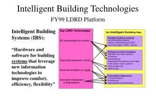
Major building systems • HVAC • Lighting • Energy/power • Communication • Plumbing • Fire Safety • Security
Introduction Building • Components are live – each has its own life cycle • Ideal design conditions are assumed to be throughout the entire life cycle • Interrelationships change with both time and events • No monitoring for detection of deterioration • Preventive maintenance – often wasteful & harmful • Experts in the field are few • Digital devices are still proprietary • Interoperability across AEC/FM • New open systems are coming
Modeling Recognizing functions of every space and needs of its occupants. • Definition of generic model templates • Generation of instance models based on specific configurations • Integration of context-dependent tasks in operations that are adaptive to dynamic environment with real-time data search and access and rule-based control
StructuralDescription Network/Spatial Structure university_C.campus_W.campusnet_E.hall_X.system_H.zone_Z.level_V.room_R System system_H.configuration_G.process_P.loop_L.device_D.point_S.parameter_T Subsystem/Process controlloop_L.controller_R.point_B
Client/Server Architecture Old Devices Devices Console Console Data Storage Application Application
BLIS Building Lifecycle Interoperable Software Project
BACnet Objects • Analog Input • Analog Output • Analog Value • Averaging Object • Binary Input • Binary Output • Binary Value • Calendar • Command • Device • Event Enrollment • File Object • Group Object • Life Safety Point • Life Safety Zone • Loop Object • Multi-state Input Object • Multi-state Output Object • Multi-state Value Object • Notification Class Object • Program Object • Schedule Object • Trend Object
Component Model HVAC system IfcBuilding ifcSpace Duct, Pipe Position, location Volume ifcElement Air, Water, Steam Energy, enthalpy, Heat, motion, flow Temperature, pressure ifcObject supplyAirObj, returnAirObject, mixedAirObject ifcControl ifcController ifcDamper ifcFan ifcCoil ifcFlowSegment ifcFlowController ifcFlowTerminal ifcLoop ifcActuator ifcChiller ifcBoiler ifcProcess ifcPump ifcValve ifcSensor
ControlLoop – generic template Major components: • Medium: air, water, energy in duct, pipe, lines • Controlled Device/object: Heating coil, cooling coil, humidifier coil, fan • Control Device: damper, valve, switch • Actuator/Drive: var. speed motor • Controller • Sensor Medium Sensor Controlled device Control device Actuator Controller
How smart can it be? Intelligent behavior • Automatic model configuration - based on the currently existing components and their respective forms and functions. • Operation adaptive to dynamic environment • - real-time data search and access • - model-based and rule-based control
Console IBS Architecture AEC/Vendor/Regulatory Documents PPCL Programs CAD DXF/DWG Layout/Layer Reasoner System Modeling VISIO EXPRESS Energy BLIS-XML Rule Generator Building Services Service & Building Selection Operating Maintenance Repair Monitoring Reporting FDD Service request KB IE Monitoring Diagnosis DB DB Message Routing Report Generation Work Control Center
Background • Rule-based expert systems for fault detection and diagnostics (FDD) applications have been implemented • Rules can be defined by carefully analyzing the logic of a DDC program in terms of both the normal and abnormal states of the affected subsystem on a given input. • Existence of expert knowledge in mature engineering and technology fields.
Motivation for new solution • Portability The rules developed in the past are usually created with the assistance of the maintenance personnel, and they often reflect the specifics of a particular HVAC, such as containing hard coded device names. • Scalability The rules are dependent on the target system configuration, but there are many differences in system configuration from building to building. • Webability The captured domain knowledge not accessible (interoperable or exchangeable) in networked and distributed environment such as the Internet.
The Main Goal To provide a framework for automatically generating FDD expert systems rules for any particular HVAC system and integrating the expert systems into the current networked, client-server, web-based environment.
Proposed Solution To use the web services technology, such as the Extensible Markup Language (XML) and the Resource Description Framework (RDF) and the industry standards, such as the Industry Foundation Classes (IFC) from the International Alliance for Interoperability (IAI).
FDD XML/RDF File Server Database Server Expert System Engine & Knowledge Base Server FDD App Distributed computing FDD XML/RDF File Server DB Servers FDD Client Expert System Engine Knowledge Base Server
Console System Modeler AEC/Vendor/Regulatory Documents PPCL Programs CAD DXF/DWG Physical system RT data Layout/Layer Reasoner System Modeling VISIO EXPRESS Energy BLIS-XML Rule Generator Building Services Service & Building Selection Operating Maintenance Repair Monitoring Reporting FDD Service request KB IE Monitoring Diagnosis DB DB Message Routing Report Generation Work Control Center FDD Module
Desired procedure: 1. The operator requests information about an HVAC from the BLIS-XML/RDF file server. The server responds with two files: (a) BLIS-XML file of a specified HVAC system and (b) RDF file. 2. From the operator’s computer, the BLIS-XML and RDF file are automatically sent for parsing and storing on the expert system engine server. 3. An agent on the expert system engine server uses the two files to parse and generate expert system rules for each HVAC process based on the process model. 4. The operator uses a browser to make a connection to the expert system engine server to specify for which HVAC system FDD should be performed immediately or according to a schedule. 5. The expert system engine server performs FDD immediately or according to a schedule and sends the results to a computer display, pager, SMTP server, etc.
The necessary components for implementing the above procedure of generating expert system rule automatically: (1) A generic fault model for each HVAC process; (2) RDF, as a method for associating an HVAC element with its real-time operational value; (3) IFC, as a standard capable of describing an HVAC system; (4) A software agent that will apply the process model to a given HVAC system to generate expert system rules; and (5) An expert system engine to parse the rules and generate inference results in the form of warnings if faults are present.
Resource Property Value Mixed_Air/Damper1 Percent open URL_1 URL 1 Location www.uc-dbserver/URL_1 Return_Air/Fan Rotation speed URL_2 URL_2 Location www.uc-dbserver/URL_2 … … … RDF structure
XML-IFC description of the sample process model <IfcSensor XMLID="i19" PredefinedType="HVACSENSOR" ConnectedTo="i20" ObjectType="Humidity sensor for measuring the temperature of the air after it has been mixed, warmed or cooled" /> <IfcController XMLID="i20" ControlElementID="5" ConnectedTo="i21" ObjectType="controls the humidifier valve actuator" /> <IfcActuator XMLID="i21" PredefinedType="PNEUMATICACTUATOR" ConnectedTo="i22" ObjectType="humidifier valve 1 actuator" /> <IfcValve XMLID="i22" ValveType="GATE" ObjectType="humidifier valve 1" /> <IfcActuator XMLID="i23" PredefinedType="PNEUMATICACTUATOR" ConnectedTo="i24" ObjectType="humidifier valve 2 actuator" /> <IfcValve XMLID="i24" ValveType="GATE" ObjectType="humidifier valve 2" /> <IfcRelAssemblesElements XMLID="i25" RelatingElement="i20" RelatedElements="i21 i23" />
Implementation • The system is implemented with the Java-based open source solution. • The expert system component consists of Jess (Java Expert System Shell), which is in its core a collection of Java classes • Jess provides easy to use mechanisms for creating Java objects, accessing their variables and calling their methods. • In addition, it is possible to start the Jess engine from Java code, which gives the programmer the ability to redirect the output of the engine to any valid Java output stream (e.g., TCP/IP socket).
Jess also takes advantage of the Java Bean™ technology, a form of inter-process communication, which enables a Java application to implement the event driven model. • A Java Bean is a Java object that generates (or “fires” in Java terminology) predetermined events. • If a Java Bean has one or more “listening” objects attached to it, they will be able to “hear” the events and take appropriate actions. • All “listeners” must first register with the Java Bean to receive fired events. Jess can easily register to become a “listener” with such a class and update the changed information in the appropriate slot of its template (a named entity that contains a list of facts). • As soon as Jess modifies a fact on its fact list, it re-runs all the rules in its knowledge base.
The FDD rules from the prior expert system shell, M4, were converted into the Jess language and a Java Bean based template was created to retrieve parameters relevant to the process from the database. • The connection to the database was established with the help of the JDBC-ODBC Bridge, which provides the necessary API for Java programs to make connection to ODBC sources on Windows based computers and use SQL for querying the tables in question.
A simple message exchange protocol of a client-server model was implemented: - A TCP/IP server is launched and listens on a port for applet connections. - As soon as one connection is established, it spawns an object of the class “processor” passing the obtained communication socket as the parameter. - The processor immediately enters a new thread waiting for commands from the applet. - The server meanwhile is able to accept new connections creating a processor object for each case.
GUI The last step is to create a Java applet to allow the Internet user to view the output of the FDD. After the server receives the request from the incoming connections from the applet, the output of the expert system engine would be re-routed to the client side of the connection into a text area located in the applet.
Conclusion • A real-world application of HVAC FDD system was used. • The main steps and the major components needed for design and deployment of web-based intelligent systems are highlighted. • For an application in other domains, expert knowledge needs to be extracted, modeled, and represented in knowledge base. The knowledge of experienced domain workers is critical. • Overall, we have considered and demonstrated successfully that practical configuration mapping, expert system rule generation and real-time data access can be accomplished with the off-the-shelf web tools and today’s component technologies.
Conclusion • There is a need for a practical solution to implement intelligent behavior of systems that are networked and digitally controlled. • It is important to use expert knowledge and salvage the knowledge in the existing expert systems and readapting it into the distributed computing model of the present time. • Expert system technology is still used to let the computer “reason” about what it “sees” based on a generic model for each of the modeled processes and real-time data. • Application software development for upcoming building open systems is coming of age.