Download
1 / 57
570 likes | 575 Views
This review discusses recent progress in the development of X-ray interferometer for beam emittance measurement, including the use of a wide aperture interferometer and an inverse-contrast interferometer. It also proposes the implementation of an X-ray interferometer at ALBA to measure the beam size of the FCC-ee accelerator.

E N D
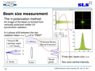
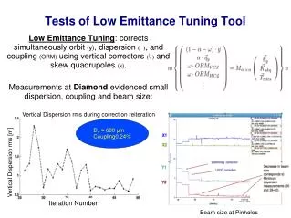
Beam emittance (size) diagnostic Recent progress T. Mitsuhashi KEK
Review of X-ray interferometer • Possibility for bunch by bunch beam size measurement • Undulator • wide aperture interferometer • Inverse-contrast interferometer • 3. Proposal for X-ray interferometer at ALBA
175GeV r=11590.8m 0.1nm Divergence of beam Order of 10-7rad Divergence of SR Order of 10-5rad q in rad
Expected spectrum from the bending magnet FCC-ee 45GeV 175GeV Brightness (photons / mrad2 1%bandwidth) Frequency integrated power 174W/ 20mrad for 175GeV 172W/20mrad for 45GeV Photon energy (keV)
Character of bending magnet in FCC-ee 24.858m or 2.144mrad Bending angle of 2.144 mrad is 100 times larger than tail to tail opening of SR at 0.1nm (0.002mrad). So, this bend is classified as long magnet. TR from magnet edge is week enough in X-ray region. Bending radius 11590.8m
Extraction of hard X-rays from the ring • Light source • use last bending magnet in Arc.
100m 24.858m 2.144mrad 50m 107.2mm 1.072mrad 53.6mm Geometrical condition for the extraction of SRfrom the last bending magnet Enough separation between orbit and extraction structure of the vacuum duct is necessary to escape from corrective effect. Some similar structure such as crotch absorber and branch optical beam line seems necessary to protect the crotch of the vacuum chamber from strong irradiation of SR. Bending radius 11590.8m
K-edge filter Double slitD=20-few100mm, a=8mm Be-window 100m 50-100m Simple double slit X-ray interferometer (Young type)
175GeV r=11590.8m Double slit location We do not need selection of polarization Iv / Ih =0.016 q in rad
Spatial coherence vs. beam size D=300um, f=100m l=0.10nm g Beam size (mm)
Double slit of interferometer will not miss the beam size information Divergence of SR Order of 10-5rad Divergence of beam Order of 10-7rad
Double slit interferometer (Young type) with total reflection mirror
Expected interferogram for g=0.65 (beam size of 5mm at 100m) Double slit a=8mm, D=300mm f=100m Monochromatic l=0.1nm
Absorption of Krypton gas K-edge filter (1 atm, 100 mm pass). Krypton gas filter has a nice window around 10keV
Shift in two optical axis Dl/l=20%
Background subtraction problem Log scale plot for the interference fringe with two diffraction envelopes of slit
Escape from the shift in two optical axis Elliptically deformed total reflection mirror
Interferogram by elliptically deformed total reflection mirror
Possibility for bunch by bunch beam size observation Rough estimation from experience for interferometry using visible light in the ATF
ATF has 1nc in the single bunch. Our experience in before, light intensity of 50 bunch is necessary for beam size measurement. Still many parameters are not precise to make reliable estimation, but roughly speaking about 1-2 order more intensity will necessary for bunch by bunch beam size observation. Wide aperture optics (so-called coded aperture is using in the super B factory in the KEK)
Increase flux density of the SR by inserting some undulator (an assumption) Parameters of Undulator
Spectrum from Undulator (not including energy spread of the beam 0.018nm at 175GeV 0.275nm at 45GeV
Problem Simple fixed period undulator cannot cover the energy range from 45GeV to 175GeV. Questions Double slit can accept high flux density? Is there any space for undulator(3-4m)?
Fresnel transfer Fourier transfer
a=10mm D=30mm a=38mm D=30mm
Diffraction treatment for interferometer -a a -a a -D/2 D/2
Diffraction by this aperture is given by Fourier transfer of E Then the intensity is given by square of E
This treatment is assuming the spatial coherence will be 1. When the spatial coherence is not equal to 1 as
This large aperture interferometer can use under following condition. Since we can enlarge the slit width 10-50 times more, this method is very useful for increase the intensity.
Using Babinet’s principle, Synthesize of two mask is given by, Then obstacle mask is given by Double slit mask is given by, Then double obstacle mask is given by
The intensity is given by square of u, I0is intensity of aperture having no double obstacle, Iap1, Iap2are intensities double slit corresponding to double obstacle
u0uap1, u0uap2are interference between disturbance of aperture having no obstacle and double slit corresponding to double obstacle. uap1uap2 is interference between double slit corresponding to double obstacle. Observing the intensity in infinite distance (very far away), the first 3 terms are localized in center (width of order of full aperture diffraction) , and last 3terms gives same intensity distribution ob double slite interferometer
When we observe the intensity distribution at diffraction width of single slit is almost same as opening of I0 , u0uap1, u0uap2those are interference between disturbance of aperture having no obstacle and double slit corresponding to double obstacle will appear, and it’s intensity is enhanced by u0. This can contribute intensity increase in observation. But we need check experimentally.
Proposal for test of X-ray interferometer at Long range beam line ALBA T. Mitsuhashi and Ubaldo Irizo
Source point to double slit 33.5m 10m will available for interferometer
7th harmonics at 11.06KeV
Double slit D=10-100mm,2 a=8mm 33.5m 7-10m Simple double slit X-ray interferometer (Young type)
Spatial coherence of X-ray with beam size of 5.5mm l=0.1nm L=33.5m
Diffraction from single opening of the interferometer Intensity of diffraction is given by Fresnel transform of pupil function F of the single opening of the double slit.
t=f/(a2/l)<1 t=f/(a2/l)>3 Fresnel like region Fraunhofer like region In the case of ALBA, l=0.1nm, a=8mm Fraunhofer region > 1.92m