Download
1 / 35
350 likes | 352 Views
Explore further requirements using use case driven analysis and system sequence diagrams. Learn to define use cases and develop models for object-oriented requirements.

E N D
Use Case Driven Analysis Chapter 5 Exploring further Requirements Use Case Use Case Description System Sequence Diagram
Revision • The basic objective of requirements definition is understanding: • users’ needs, • how the business processes are carried out, • and how the system will be used to support those business processes.
Overview • This chapter is in a way a continuation of what we were doing: understand and define the requirements for a new system using object-oriented analysis models and techniques. • Learning to build models is a fairly difficult task requiring focus and practice by you, the students: the famous THREE P’s: • Practice, practice, practice!
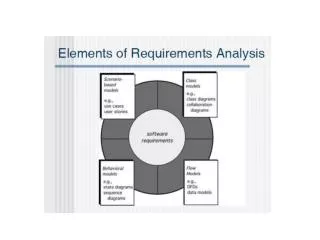
Overview (continues) • The object-oriented approach uses an iterative approach to development, which identifies some of the requirements, then does some preliminary design and implementation, and then iterates again and again through requirements, design, and implementation. • The key point to emphasize is that every system has both data and processes. • The data portion comes from the idea of “things,” also known as objects in object-oriented development. The model used to describe the objects is the class diagram. It provides the structural information about the objects in the system. • The models used to describe the processes are the use case diagrams and related models that provide detailed information about the use cases
Overview (continues) • You should be aware that the line between object-oriented analysis and object-oriented design is somewhat fuzzy because the models that are built to define requirements during analysis are refined and extended to produce a system design. • Also to realize how UML diagrams work together to define functional requirements for the object-oriented approach
UML: • Static models • Domain Model class diagram • Dynamic models • dynamic behaviour means the behaviour of the system when it is running /operating. • So only static behaviour is not sufficient to model a system, but also the dynamic behaviour . • In UML there are five diagrams available to model dynamic nature: use case, activity, sequence, collaboration and statechart.
Objective • We extend the concepts associated with both activity diagrams and use case definitions: use case descriptions: • Brief, intermediate, full description • (do not forget our friend: EVENT Table!!) • We introduce the concept of sequence diagrams through a simplified version of sequence diagrams called system sequence diagrams, or SSD • Next time we will do the state machine diagram. Nearly covering ALL analysis models!
LO: • Understand the models and processes of defining object-oriented requirements. • Be able to develop use case diagrams, and fully descriptive use cases. • Develop system sequence diagrams. • Develop state machine diagrams to model object behavior.
Use Case (Revision) • A use case is simply a further refinement of the information provided by each event in the event table. A business event focuses on what is happening in the business. A use case, however, has a narrower focus and emphasizes what the automated system must support. • Because a use case is focused on the automated system, an actor is the role of the person or thing that initiates the computer activity. We emphasize this point by saying that actors have hands. • The naming of use cases will help to identify and describe use cases. The name of the use case should be the predicate part of a sentence that begins with the actor using the system to do something. • For example, “An order clerk uses the system to ‘create a new order’.”
Scope of a use case • A use case is much like a business event. It starts with an interaction from an actor. • It ends when the system reaches a quiescent point in the processing. • For example, a sale transaction (business event) is not complete until all items are included and a total is calculated. Depending on the type of sale (cash), a payment may also be included in the transaction
A new customer wants to create an account with a company. She phones the company, and request for new account online: She enters basic customer information that is used to create a new customer. She also has to enter her addresses. She then enters her credit/debit card information. With this information the system creates an account, verifies authorization for credit/debit card information, and return valid customer account details.
Procedure to follow: • Draw an entity-activity table: • EntityActivity ????? • Identify the events:
Use case: Scope/Detail • Page 64 in the prescribed book, identify 3 levels of detail: • One analyst will identify a use case as typing in a customer name on a form • Second analyst might identify a use case as the entire process of adding a customer • A third analyst might even define a use case as working with customers all day: add customers, update customers, delete customers. • No 1 is too narrow, no 3 too broad and no 2 defines a complete user goal, which is the right level of analysis. Is the usecase useful? (Don’t confuse use cases with processes.)
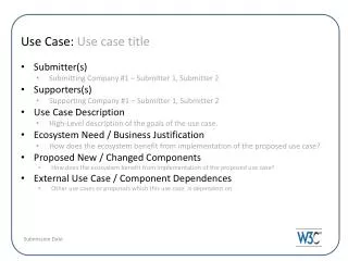
Fully Developed Use Case Descriptions • To create a comprehensive, robust, system that truly meets user’s needs; we must understand the detail steps of each use case. (sequence of steps to complete the business process0 • Use case name: a unique name for this use case • Scenario: sometimes several variations of the business steps exist within a single use case. Example: updating info over the phone OR when customer visit shop and do it personal: use case instances.
(continues) 3. Brief Description: a one or two sentence description of the results of the use case 4. Actors: all those actors who use this use case 5. Related use case: any included use cases, or use cases that “include” this one 6. Stakeholders: other persons, other than the actors, who have an interest in the results or successful completion of this use case
(continues) 7. Preconditions: The state of the system before the use case begins, especially any required conditions of the database. Conditions that must be true in order for the use case for fire successfully 8. Postcondition: the state of the system at the successful completion of the use case, especially any updates to the database
(continues) 9. Flow of activities: a step by step sequence of the actions by the actor and the system internal to the use case 10. Exception conditions: any exception conditions that cause the system not to follow the expected flow of activities or that cause the use case to terminate abnormally • Usually the flow of activities is the most difficult part to develop, but also assists the analyst and the user to understand the requirements more deeply
Think more deeply • Ask the following Q’s when developing workflows are: • Does the workflow need to test the preconditions to ensure they are true? • Does the workflow need to find and verify the correct objects to include in the process? • What steps are needed to ensure that all the post-conditionsare met? • Are there multiple instances of objects or relationships that will require looping? • Are there decision points that result in different postconditions or different alternatives of postconditions? • Test each step in the sequence and ask, “Can anything go wrong, and what are the remedial activities?”
System Sequence Diagram: • Neither activity diagrams nor fully developed use case workflows focus on the flow of data. • The UML model that captures the input and output data is a system sequence diagram (SSD). • The easiest way to develop an SSD is to use an activity diagram. Each time an arrow leaves the actor swim lane and enters the system swim lane, there is a potential input. Conversely, every time an arrow goes from the system to the actor, there is the possibility of an output occurring. Thus, SSDs are a natural outgrowth of an activity diagram.
System Sequence Diagram (SSD) • A UML sequence diagram • Special case for a sequence diagram • Only shows actor and one object • The one object represents the complete system • Shows input & output messaging requirements for a use case • Actor, :System, object lifeline • Messages: [true/false condition] return-value := message-name (parameter-list)
SSD: Syntax and Semantics • Message: • The name of an input message should describe a service requested from the system. Messages will eventually be used to help identify and name methods associated with the objects. • Because a method represents the invoking of a service, it is good practice to assign the message the same name as the eventual method. For example, “addItemToOrder” describes a specific service that the actor wants the system to perform
SSD: Message • Model consistency: • The data parameters must be consistent with the attributes from the identified classes. For example, if a customer class has an e-mail address as an attribute, it must be passed via a parameter in an input message.
Steps for Developing SSD • Identify input message • See use case flow of activities or activity diagram • Describe the message from the external actor to the system using the message notation • Name it verb-noun: what the system is asked to do • Consider parameters the system will need • Identify any special conditions on input messages • Iteration/loop frame • Opt or Alt frame • Identify and add output return values • On message itself: aValue:= getValue(valueID) • As explicit return on separate dashed line
Homework (Ch 5, Problem 1) • Quality Building Supply has two kinds of customers: contractors and the general public. Sales to each are slightly different. • A contractor buys materials by taking them to the contractor checkout desk. The clerk enters the contractor name into the system. The system displays the contractor information, including current credit standing. • The clerk then opens up a new ticket (sale) for the contractor. Next, the clerk scans in each item to be purchased. The system finds the price of the item and adds the item to the ticket. At the end of the purchase, the clerk indicates the end of the sale. The system compares the total amount against the contractor’s current credit limit, and if it is acceptable, finalizes the sale.
Homework • The system creates an electronic ticket for the items, and the contractor’s credit limit is reduced by the amount of the sale. Some contractors like to keep a record of their purchases, so they request that the ticket details be printed out. Others aren’t interested in a printout. • A sale to the general public is simply entered into the cash register, and a paper ticket is printed as the items are identified. Payment can be by cash, check, or credit card. The clerk must enter the type of payment to ensure that the cash register balances at the end of the shift. For credit card payments, the system prints out a credit card voucher that the customer must sign.
Problems: • Draw an entity-activity table • Develop an event table • Draw a use case diagram • Draw an activity diagram • Develop a fully developed use case description • Draw a SSD