Download
1 / 2
30 likes | 65 Views
Looking for Roller Blinds in Australia? Perth Blinds manufactures wide choice of custom- made Wired Motorised Roller blind. With us, you find some inspiration for the perfect design for your home or workspace. Our employees are skilled and backed with years of experience in the window coverings field.

E N D
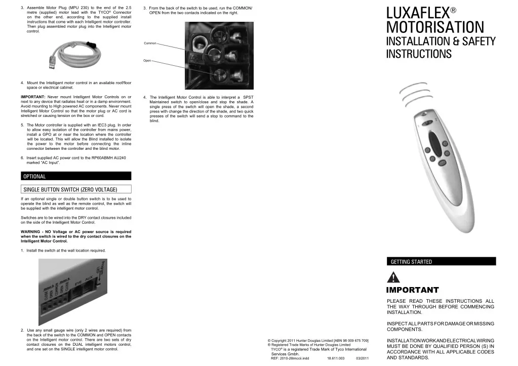
LUXAFLEX® MOTORISATION INSTALLATION & SAFETY INSTRUCTIONS 3. Assemble Motor Plug (MPU 230) to the end of the 2.5 metre (supplied) motor lead with the TYCO® Connector on the other end, according to the supplied install instructions that come with each Intelligent motor controller. Then plug assembled motor plug into the Intelligent motor control. 3. From the back of the switch to be used, run the COMMON/ OPEN from the two contacts indicated on the right. Common Open 4. Mount the Intelligent motor control in an available roof/floor space or electrical cabinet. IMPORTANT: Never mount Intelligent Motor Controls on or next to any device that radiates heat or in a damp environment. Avoid mounting to High powered AC components. Never mount Intelligent Motor Control so that the motor plug or AC cord is stretched or causing tension on the box or cord. 4. The Intelligent Motor Control is able to interpret a SPST Maintained switch to open/close and stop the shade. A single press of the switch will open the shade, a second press with change the direction of the shade, and two quick presses of the switch will send a stop to command to the blind. 5. The Motor controller is supplied with an IEC3 plug. In order to allow easy isolation of the controller from mains power, install a GPO at or near the location where the controller will be located. This will allow the Blind installed to isolate the power to the motor before connecting the inline connector between the controller and the blind motor. 6. Insert supplied AC power cord to the RP60ABMH AU240 marked “AC Input”. OPTIONAL SINGLE BUTTON SWITCH (ZERO VOLTAGE) If an optional single or double button switch is to be used to operate the blind as well as the remote control, the switch will be supplied with the intelligent motor control. Switches are to be wired into the DRY contact closures included on the side of the Intelligent Motor Control. WARNING - NO Voltage or AC power source is required when the switch is wired to the dry contact closures on the Intelligent Motor Control. 1. Install the switch at the wall location required. GETTING STARTED IMPORTANT PLEASE READ THESE INSTRUCTIONS ALL THE WAY THROUGH BEFORE COMMENCING INSTALLATION. INSPECT ALL PARTS FOR DAMAGE OR MISSING COMPONENTS. 2. Use any small gauge wire (only 2 wires are required) from the back of the switch to the COMMON and OPEN contacts on the Intelligent motor control. There are two sets of dry contact closures on the DUAL intelligent motors control, and one set on the SINGLE intelligent motor control. INSTALLATION WORK AND ELECTRICAL WIRING MUST BE DONE BY QUALIFIED PERSON (S) IN ACCORDANCE WITH ALL APPLICABLE CODES AND STANDARDS. © Copyright 2011 Hunter Douglas Limited [ABN 98 009 675 709] ® Registered Trade Marks of Hunter Douglas Limited TYCO® is a registered Trade Mark of Tyco International Services Gmbh. REF: 2010-26lmccii.indd 18.611.003 03/2011
2. Depending on the required finish, the diameter of the hole can be large enough to allow only the Flex cable to be run through the hole into the roof space, or the hole diameter can be made large enough to allow the entire TYCO® Plug to be pushed back up into the reveal to conceal the plug completely. Configuration layout for a DUAL intelligent motor control GUIDELINES FOR CERTIFIED ELECTRICIANS MOTOR WITH TWO BUTTON SWITCH Overview SAA Approval Number SAA100223, SAA090975, C-Tick N19673 When the installation package contains a motor tail and 2 button Clipsal Saturn Series Switch, the blind will be controlled via simple two button operation. DESCRIPTION 3. The rubber stopper must be left on the end of the exposed cable and the power isolated until the blind installer has connected the blind to the system and secured the in-line connectors together. Button 1 (The lower button) will supply power to the blind motor. (240V AC). The Model RP60ABMH AU240 and RP60ABMH2 AU240 Motor Controls are designed to be used with any standard 240V bi-directional motor that has built-in travel limits. The motor must have power, direction 1, direction 2, and ground connection wires. This system is designed for INTERIOR USE ONLY. When the blind motor has power supplied the (optional) LED light can be wired to illuminate, indicating that power has been supplied. WARNING - DO NOT parallel wire motors together. Doing so will cause damage to the motor. WARNING - The Inline connector must have power disconnected before connecting the blind motor. Please observe the safety warning on the supplied cable. Button 2 (the top button) acts as a direction change, and switches the UP/DOWN wire from the motor. SAFETY Configuration layout for 2 x DUAL intelligent motor controls bussed together. INTELLIGENT MOTOR CONTROL (SINGLE OR DUAL) Button 2 Direction WARNING - Never install this product with power connected. DISCONNECT FROM POWER SUPPLY before installing or adding accessories to this device. Button 1 Supply Power Overview WARNING - EVALUATED FOR FIRE AND SHOCK ONLY, NOT ENTRAPMENT. READ THESE INSTALLATION INSTRUCTIONS FOR LISTED APPLICATIONS AND LOCATION. When the installation package supplied is for remote control operation of the motorised blind, the following items will be supplied: WARNING - Prior to installation inspect all parts for damage or missing components. Two Button Switch Control Wiring Diagram 1 (or more) x intelligent motor control (single or dual) WARNING - To Reduce the Risk Of Fire, Electric Shock, Or Injury To Persons, Installation Work And Electrical Wiring Must Be Done By Qualified Person(s) In Accordance With All Applicable Codes And Standards. 1 x IEC3 power cord for Intelligent Motor Control. (1 per intelligent motor control) 1 x Flex cable tail with TYCO® Plug (1 per motorised blind) WARNING - To Reduce the Risk of Fire and Electric Shock, Install This Controller Only With Listed Window Shade, Projection Screen or Projector Lift Operator(s) Rated Maximum 2.0 amps at 240V Each. 1 x RF Receiver (always connected in the EYE socket of the intelligent motor control) Overview 1. Identify the assigned channel number of the intelligent motor control (indicated with black marker on the side of the controller). WARNING - • This appliance is not intended for use by persons (including children) with reduced physical, sensory or mental capabilities, or lack of experience and knowledge, unless they have been given supervision or instruction concerning use of the appliance by a person responsible for their safety. 1 x RF Remote control (pre programmed) INSTALLATION OPTIONAL 1. One or Two button switch for optional Dry Contact control of the blind. 1. The supplied Flex cable with TYCO® Plug should be installed so that the PLUG is located where the blind will be installed in the window reveal. • Young children should be supervised to ensure that they do not play with the appliance. 2. 5m, 10m or 20m 4cc BUS cable for linking Intelligent Motor controls together. INSTALLATION The following diagram illustrates an overview of the connected system. 2. Install supplied Flex cable with TYCO® Connector at each window location. This Document will outline installation guidelines for installation of: It is important to make note of the number that has been indicated on the Intelligent Motor control. • 2-Button Switch Control (240Volt supply and switching) The number (1, 2, 3 or 4) corresponds to the channel number on the remote control. • Remote Control with Intelligent Motor control (Single or Dual) • Remote Control with Intelligent Motor control and optional switch, one button or two button (zero voltage dry contact switching) If you are unsure of the controller location, please contact the local LUXAFLEX® Dealer. The controller must be installed and cabled (with the supplied flex cable and Tyco® Connector) to the blind that will be controlled from the channel number indicated on the controller.