Download
1 / 1
10 likes | 131 Views
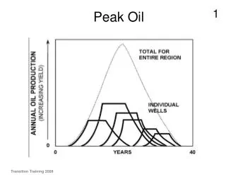
B field at center of coil (arb units). Graph of AC field with 1 coil powered. 0 3.3 6.6 10 13.3 16.7 20 23.3 Time (ms). 0 3.3 6.6 10 13.3 16.7 20 23.3 Time (ms).

E N D
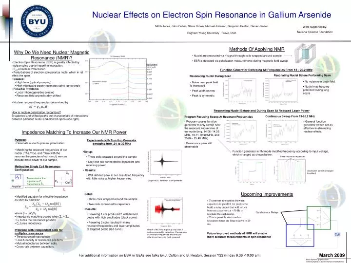
B field at center of coil (arb units) Graph of AC field with 1 coil powered 0 3.3 6.6 10 13.3 16.7 20 23.3 Time (ms) 0 3.3 6.6 10 13.3 16.7 20 23.3 Time (ms) B field at center of coil (arb units) Synchronous Relays Graph of AC field at pickup loop with 2 coils connected to capacitors. Comparison of resonant frequencies with one coil (black) and two coils (red) powered Coil Nuclear Effects on Electron Spin Resonance in Gallium Arsenide Mitch Jones, John Colton, Steve Brown, Michael Johnson, Benjamin Heaton, Daniel Jensen Brigham Young University Provo, Utah Work supported by: National Science Foundation Methods Of Applying NMR • Why Do We Need Nuclear Magnetic Resonance (NMR)? • Electron Spin Resonance (ESR) is greatly affected by • nuclear spins due to hyperfine interaction. • Beffα Nuclear Polarization. • Perturbations of electron spin polarize nuclei which in return affect the spins. • Causes: • High laser (optical pumping) • High microwave power resonates spins too strongly • Possible Problems: • Local inhomogeneities created • Resonant field unpredictably shifted • Nuclear resonant frequencies determined by • How is nuclear polarization recognized? • Broadened and shifted peaks are characteristic of interactions between polarized nuclei and electron spins (see right). • Nuclei are resonated via rf signal through coils wrapped around sample • ESR is detected via polarization measurements during magnetic field sweep Function Generator Sweeping All Frequencies From 13 - 26.2 MHz Resonating Nuclei Before Performing Scan Resonating Nuclei During Scan • No noise near peak field. • Nuclei may become polarized during long scans • Noise near peak field is increased • Peak width narrow • Peak is symmetric Resonating Nuclei Before and During Scan At Reduced Laser Power Continuous Sweep From 13-26.2 MHz Program Focusing Sweep At Resonant Frequencies • Program causes function generator to only sweep near the resonant frequencies of our nuclei (e.g. 14.06 -14.26 MHz, 19.71-19.99 MHz, and 25.04 - 25.40 MHz). • Resonance peak still observable • General function generator sweep not as effective in eliminating nuclear effects. Impedance Matching To Increase Our NMR Power • Purpose: • Resonate nuclei to prevent polarization. • Matching the resonant frequencies of our nuclei (75As, 69Ga, and 71Ga) with the resonant frequencies of our circuit, we can provide more power to our sample. • Method for Single Coil Resonance: • Configuration: • Modified equation for effective impedance as seen by amplifier: • where β = ωZ0CT. • Impedance matching occurs when ZS = Zin • C1 tunes the resonance position • C2 tunes impedance • Problems with independent coils for multiples resonances: • Three targeted resonances • Lose tunability of resonance positions • Mutual inductance between coils. • Cross-talk between capacitors. Experiments with Function Generator sweeping from .01 to 30 MHz Function generator in FM mode modified frequency according to input voltage, which changed as shown below: • Setup: • Three coils wrapped around the sample • Only one coil connected to capacitors and receiving power • Results: • Well defined peak at our calculated frequency with little noise at higher frequencies. Three resonant frequencies (oscillation periods enlarged for effect) C1 5 11.25 17.5 23.75 30 Frequency (MHz) ZS Transmission line impedance Z0 Capacitance CT C2 Coil Amplifier ZL Upcoming Improvements • Setup: • Three coils wrapped around the sample • Two coils connected to capacitors • Results: • Powering 1 coil produced 2 well defined peaks with high amplitudes (black curve). • Powering 2 coils resulted in many resonant frequencies and lower amplitudes at targeted peaks (red curve). • To prevent interactions between capacitors in parallel, we propose to build a relay circuit that will switch between capacitors at ~50 Hz to resonate the each nuclei. • This is possible since nuclear relaxation times are long relative to 20 ms. 5 11.25 17.5 23.75 30 Frequency (MHz) Future improved methods of NMR will enable more accurate measurements of spin resonance March 2009 For additional information on ESR in GaAs see talks by J. Colton and B. Heaton, Session Y22 (Friday 9:36 -10:00 am) Bloch Spheres graphics from nodens.physics.ox.ac.uk/cmphys/correlated/cmp/