Download
1 / 20
200 likes | 361 Views
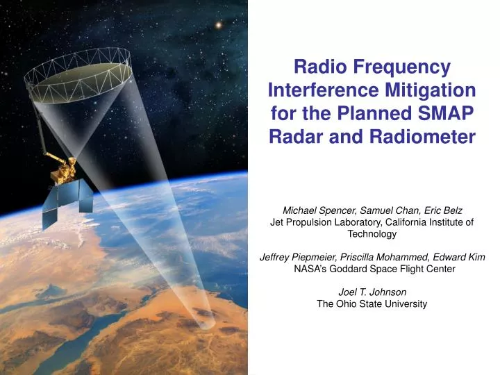
Radio Frequency Interference Mitigation for the Planned SMAP Radar and Radiometer Michael Spencer, Samuel Chan , Eric Belz Jet Propulsion Laboratory, California Institute of Technology Jeffrey Piepmeier, Priscilla Mohammed, Edward Kim NASA ’ s Goddard Space Flight Center Joel T. Johnson

E N D
Radio Frequency Interference Mitigation for the Planned SMAP Radar and Radiometer Michael Spencer, Samuel Chan, Eric Belz Jet Propulsion Laboratory, California Institute of Technology Jeffrey Piepmeier, Priscilla Mohammed, Edward Kim NASA’s Goddard Space Flight Center Joel T. Johnson The Ohio State University National Aeronautics and Space Administration Jet Propulsion Laboratory California Institute of Technology Pasadena, California National Aeronautics and Space Administration Jet Propulsion Laboratory California Institute of Technology Pasadena, California SMAP-1 SMAP-1 JPL/Caltech proprietary. Not for public release or redistribution. For planning and discussion purposes only.
Outline • Motivation • The Users of L-band Spectrum • RFI approach for SMAP radiometer • RFI approach for SMAP radar • Summary
Motivation • NASA’s Soil Moisture Active/Passive (SMAP) mission will utilize L-band radiometry and radar measurements to retrieve surface soil moisture • Passive observations in the protected 1400-1427 MHz band and active observations in the shared 1215-1300 MHz band. • Radio Frequency Interference (RFI) in these bands can impact SMAP’s ability to perform soil moisture retrievals • A significant risk to SMAP’s ability to meet mission requirements • SMOS & PALSAR experience clearly demonstrate the presence of RFI • SMAP has been assessing risk and developing methods to mitigate problems • What is the risk? • How to mitigate? • Can risk after mitigation be quantified? • This presentation provides an update on current status and plans • Focus on mitigation approaches and expected performance
Users of L-Band Spectrum • Radar Band (1215 – 1300 MHz) • Shared with other services: • Radionavigation sats (GNSS) • Radiolocation (of aircraft by radar) • Amateur • Other • Radiometer Band (1400 - 1427 MHz) • Protected Band, but: • In-band un-authorized emitters. • Susceptible to out-of-band emissions from adjacent bands.
RFI and SMAP Error Budget • Soil moisture impact on L-band Tb and NRCS is strong for bare surfaces, but sensitivity decreases as vegetation biomass/water content increases • SMAP intends to retrieve soil moisture up to 5kg/m2 VWC • Retrievals need to account for surface temperature, presence of vegetation, surface roughness, radiometric uncertainty, speckle noise, etc. • Uncertainties in ancillary information increase retrieval errors • SMAP Science Team has defined an RFI error budget allocation • 0.4 dB for radar, 0.3K for radiometer • RFI impact on error budget: • All data for pixels discarded due to detected uncorrectable RFI (or similar false alarm) • adds to data loss allocation • Partial pixel data discarded due to detection or false alarm, some retained • e.g., increases NEDT and therefore counted against RFI margin • Low-level RFI not detected • Also counts against RFI margin • Need description of RFI environment to quantify these effects
Describing the RFI Environment • Three approaches: • Predictions based on known properties of US-based radar installations • Requires assumptions about out-of-band radar emissions • Models can consider satellite overpasses, antenna rotations, etc. • Found that some emitters will produce RFI impact but locations are known and can be removed using a “pulse” detection strategy • No consideration of other emitter types • Airborne observations • On-air measurements capture any emitters in observed locations • Include systems to capture detailed emitter properties • Limited to locations observed, collaborate with international partners to expand datasets collected • Satellite observations • SMOS providing information on RFI locations (~40 km spatial resolution), power levels, angular/polarimetric properties but very limited time/frequency resolution • Utilize Aquarius also when available (~100 km spatial resolution), fixed angle, polarimetric properties, improved time resolution
SMAP Airborne RFI Campaigns • JPL’s PALS instrument with RFI backends • ~ 62 flight hours in US • Characterize time/frequency/kurtosis properties • Map observations into predicted satellite RFI levels Spectrogramduring overflight of New York City Statistics show low-level RFI common
How to Mitigate? • Due to clear RFI risk to meeting soil moisture accuracy requirements, SMAP Science team recommended implementing an RFI backend------1st time for a satellite radiometer • On-board digital processor will produce and downlink • First 4 signal moments at ~250 μsec time resolution Th, Tv, T3, T4 • Brightness in 16 x 1.5 MHz frequency sub-channels every ~ 1 msec • All 4 Stokes parameters and Kurtosis • Significant increase in radiometer data rate • Can detect RFI using • Time domain methods (pulses) • Frequency domain methods (narrow band) • Kurtosis methods (non-thermal noise) • T3, T4 polarization • Only pieces of the observation removed if RFI is limited in time or frequency • Development on schedule for SMAP deployment 1 2 3 …. 16 24 MHz @ 1.4 GHz
Initial Performance Study: Fullband • Generated simulated thermal noise into SMAP 96 Ms/s ADC, add pulse sinusoidal RFI of specified amplitude, pulse length, and duty cycle • Simulate SMAP Fs/4 downconversion, LPF, decimation by 4, and fullband moment computation for I and Q signal components • Produced for 32 ~250 μsec sub-intervals for one 8 msec integration period • RFI detected using both “pulse” and kurtosis methods; requires threshold choice
Initial Performance Study: Sub-channels • 16 point windowed FFT also performed • First through fourth moments of I/Q computed after FFT • Enables “cross frequency”, “peak-picking”, “sub-band pulse” and “sub-band kurtosis” methods • Cross-frequency utilizes “RFI-free” Tb estimate using 12 smallest of 16 sub-bands
SMAP Radar RFI sources • The 1215-1300 part of the L-band spectrum is heavily used by various systems around the world. • Radio navigation signals from multiple satellite constellations are broadcasting continuously. • GPS • GLONASS • COMPASS • GALILEO • Other terrestrial sources…. • Amateur (weak & strong CW, SSB, NBFM, data, video) • Strong beacons • Wide variety of signals & modulations worldwide. • Long-range radiolocation radars. Relatively narrow-band pulsed systems. • FAA (ARSR, CARSR) • DoD (FPS series) • Other U.S./Canada radars in data base. • Similar radars around the world.
Summary of RFI Mitigation Design (1 of 2) • Many observed narrow band (< 4 MHz) emitters. • Emitters appear to be “stationary” in frequency, geographic position. • Mitigation strategy: • Ground-commandable, tunable carrier frequency to hop frequencies and avoid PARTICULARLY BAD spectral areas. • RFI which is still encountered (estimated to be approximately 10% of time) will be filtered in ground processing. • Other design consideration is that receiver should not compress/saturate for strong out-of-band sources. RF Bandwidth (100 MHz acceptance) Requirement/Allocation: RFI shall not contribute more than 0.4 dB 1-sigma to the backscatter measurement. Up to 2% of the data can is allowed to be flagged “bad data” where RFI is too excessive to mitigate. IF, Digital System Bandwidth, 5 MHz HH noise HV 1 MHz RFI
Summary of RFI Mitigation Design (2 of 2) • Ground filtering approach: • Primary filtering approach is to simply excise affected range lines (which exceed some threshold) and form image without them. • Analysis shows that if pulsed interference is in as many as 15-20 range lines, it can be reliably detected. • Analysis shows that approximately 15 range lines can be lost without violating 0.4 dB requirement for that one measurement. • CW sources can be easily detected and notched in the frequency domain, provided that the BFPQ does not get saturated (Interference-to-Signal ratio > 14 dB). PALSAR example Successive pulses Power threshold One vertical cut of left image Range lines
Modeling of Ground Based Emitters • Simulation of RFI environment using characteristics of known emitters and SMAP instrument parameters. • Advantages: Utilizes SMAP antenna pattern and scan characteristics. Capable of simulating known future systems. • Disadvantages: Only complete data set of emitters available to us (thus far) is over North America. Difficult to obtain all necessary parameters of interfering radars. • Key results to date: • Simulation predicts probability of exceeding threshold for 0.4 dB interference (-110 dBm average power in any given range line) at 10% over N. America in any given 1 MHz band. • Simulation predicts probability of exceeding power level sufficient to compress front end < 0.1 %. • Simulation predicts probability of range line having at least one pulsed event exceeding power level to compress IF < 1%. • Simulation predicts generally lower probability of interference in lower part of allocation < 1260 MHz, as opposed to upper part of allocation > 1260 MHz
Assessment of Ground Emitters Using Current L-Band Data Sets • Analysis of JAXA ALOS/PALSAR data. • Advantages: Utilizes real data in band of interest. Data set has measurements from all over the globe. • Disadvantages: Antenna pattern and data collection technique very different from SMAP. PALSAR only covers 32 MHz of 85 MHz allocation. Data only valid for current RFI environment, not future. • Key results to date: • Survey of PALSAR data shows primarily pulsed emitters typical of air surveillance radars (87% of occurrences) with another 13% of occurrences miscellaneous (including CW) sources, with high concentration over urban areas. • Quantitative survey of pulsed emitters over North America indicate probability of having more than 5 SMAP range lines (out of 112) contaminated by RFI is < 1 % for any randomly chosen 1 MHz band. • Analysis of impulse response function suggests that approximately 15 range lines (out of 112) could be excised and the measurement would still meet the 0.4 dB requirement. The analysis suggests 15 contaminated range lines is a very low probability event. • Experiments to “clean up” PALSAR data using detection and filtering scheme have thus far been very successful, with residual errors < 0.1 dB.
Modeling Impact of Satellite Transmissions • Analysis of spacborne emissions from Global Navigation Satellite Systems (GNSS) • Model emissions of existing radionavigation satellite constellations (GPS, GLONASS, etc.) • Signals received by SMAP backlobes as well as signals reflected off of the Earth. • Key results to date: • GPS satellite constellation that is expected to be in place at time of SMAP mission has been modeled. • At any given time multiple GPS satellites (> 15) can be “seen” by SMAP. • Both “direct” interference into SMAP back-lobes and interference reflected off of the Earth modeled. • Interference power due to direct reception by backlobes is non-negligible but tolerable. • Reflections off of the Earth are potentially large for: • Quasi-specular scattering from the ocean. This shouldn’t be too big of a problem for land-based soil moisture measurements. • SMAP main beam coincides with GPS specular point for specular surfaces (lakes, wetlands, etc.). These conditions should rare, be easily recognizable from the noise only data. • Other GNSS systems are expected to have similar behavior as GPS.
Summary • L-band RFI is an important risk for the SMAP mission; detection & mitigation needed to meet requirements • RFI detection/mitigation baseline for radiometer: • Detection in various domains: time, frequency, statistical moments, polarization • 16 frequency sub-bands; ~300us time resolution, 4-Stokes, kurtosis • Dedicated digital backend for on-board RFI signal processing---1st time for satellite radiometer • SMOS is providing and Aquarius will provide very useful information on RFI environment • But low-level RFI detection still needs investigation • Analyses indicate radiometer RFI requirements will be met • RFI detection/mitigation baseline for radar: • Detection via power thresholding in time domain • Frequency hopping to avoid persistent severe RFI • Wide dynamic range for low probability of saturation • Additional mitigation performed in ground processing to remove remaining RFI • Studies suggest • spaceborne emitters such as GPS non-negligible but manageable. • Saturation is low probability. • Analyses indicate radar RFI requirements will be met • Next steps: • Continue refinements in RFI environment characterization and algorithms • Improve RFI modeling capability • Use SMOS, Aquarius, & airborne data to validate models • Hardware tests planned http://smap.jpl.nasa.gov/