Download
1 / 32
320 likes | 328 Views
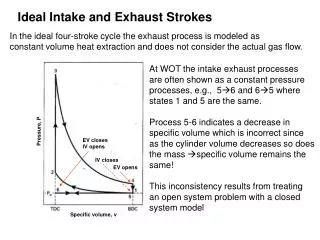
Irreversible Gas Dynamics of Intake and Exhaust Flows. P M V Subbarao Professor Mechanical Engineering Department. Design Rules for Maximum Intake Flow…. Isentropic Specific Mass flow Rate. Mass flow rate per unit area of cross section:. Size of Minimum Flow Area.

E N D
Irreversible Gas Dynamics of Intake and Exhaust Flows P M V Subbarao Professor Mechanical Engineering Department Design Rules for Maximum Intake Flow….
Isentropic Specific Mass flow Rate Mass flow rate per unit area of cross section:
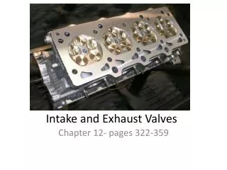
Size of Minimum Flow Area • For lower valve lift the minimum area is the valve curtain area. • For larger lifts the minimum area is the valve seat area.
Isentropic Compressible Flow Through Inlet Valve : low Lift Resource : The total pressure in the inlet manifold – Cylinder pressure
Conditions for Choked Flow Resource : The total pressure in the inlet manifold – p* When the flow is chocked:
Stages of Valve Lift The maximum valve lift is normally about 12% of the cylinder bore or 25% of .
Instantaneous Flow Area : Low Lift • For low lift valves, the minimum flow area is normal to a frustum of right circular cone. • The area perpendicular to the conical face between valve and seat is, defines the flow area. The minimum area is:
For the second stage, the minimum area is still the slant surface of a frustum of a right circular cone. However, the flow area is not perpendicular to the valve seat. The base angle of the cone increases from (900-) toward that of a cylinder. For this stage: Instantaneous Flow Area : Intermediate Lift Dm is mean diameter of seat :
Instantaneous Flow Area : High Lift • When the valve lift is sufficiently large, the minimum flow area is no longer between the valve head and seat. • It is the port area minus the sectional area of the valve stem. Then,
Local vs Average Mach Number • Choking will occur at a local Mach index of 1. • The average gas speed corresponding to choked condition is less than 1. • For highest intake flow rate, the real value of highest average Mach number ≤ 0.6.
Irreversible Flow thru Intake Valve • The real mass flow rate is always lower than the ideal mass flow rate. • At any location in a flow passage, there are two reasons for lower values of real mass flow rate: • The first reason: Actual local velocity of the flow is always less than velocity of isentropic flow. • The ratio of real velocity to ideal velocity is called as flow coefficient, Cf.
Irreversible Flow thru Intake Valve • The second reason: Only at minimum area location the area of the stream tube is equal to available area. • At other locations this ratio is less than 1. • This is called as coefficient of contraction. • For a given flow passage, the discharge coefficient, Cdis defined as Real measured mass flow rate over the ideal mass flow rate.
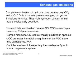
Source of flow losses in the port • Source of flow loss % of loss • Wall friction = 4% • Contraction at push-rod = 2% • Bend at valve guide =11% • Expansion behind valve guide = 4% • Expansion 25 degrees = 12% • Expansion 30 degrees = 19% • Bend to exit valve = 17% • Expansion exiting valve = 3%
Frictional Compressible Flow Through Inlet Valve • The real gas flow effects are included by means of an experimentally determined discharge coefficient CD. • The air flow rate is related to the upstream stagnation pressure p0 and stagnation temperature T0, Static pressure just down stream of the valve and a reference area AR. • AR is a characteristic of the valve design. When the flow is chocked:
General Theory : Four-mode model of flow separation in a valve gap Mode I: At low lifts (approximately L/D < (0.07- 0.09)) the flow is attached to both valve seat and sealing faces, and the discharge coefficient usually has a high value. At intermediate valve lifts (approximately 0.09 <L/D < 0.12) the flow separates from the valve but remains attached to the valve seat, and the discharge coefficient decreases..
General Theory : Four-mode model of flow separation in a valve gap At intermediate-high lifts (approximately 0.12 < L/D < 0.15) the flow separates from both valve seat and sealing faces and forms a free jet which is hardly influenced by the valve seat geometry. At high valve lifts (approximately L/D > 0.15) the flow separation from the valve seat face is more extensive; the discharge coefficient recovers slightly and decreases linearly with increasing lift
The sensitivity of CD to differences in the flow conditions in the valve gap
FUEL A I R Computation of Intake Process : SI Engine SI Engine
FUEL A I R Total Mass inhaled during Intake Process
Volumetric Efficiency : A Global Measure of Breathing Effectiveness • Volumetric efficiency a measure of overall effectiveness of engine and its intake and exhaust system as a natural breathing system. • It is defined as: • If the air density ra,0 is evaluated at inlet manifold conditions, the volumetric efficiency is a measure of breathing performance of the cylinder, inlet port and valve. • If the air density ra,0 is evaluated at ambient conditions, the volumetric efficiency is a measure of overall intake and exhaust system and other engine features. • The full load value of volumetric efficiency is a design feature of entire engine system.
True mass of Intake air in Current SI Engines • The true mass of intake air is function of • Fuel type, fuel/air ratio, fraction of fuel vaporized in the intake system, and fuel heat vaporization. • Partial pressure of air in Intake mixture pa,im. • Fuel/ air ratio (F/A). • Mixture temperature as influenced by heat transfer. • Intake mixture Temperature Tim. • Compression ratio rv. • Exhaust pressure, pe. • Duration of actual intake is less than duration inlet valve opening.
Fuel Evaporation in SI Engine Intake Manifolds • The liquid fuel is completely/partially evaporated in the inlet pipe and ports of SI engines. • The presence of gaseous fuel and moisture in the intake system reduces the air partial pressure below the mixture pressure. • For a mixture: In most of the current commercial spark ignition engines, the fresh mixture contains unevaporated fuel during the inlet process. This quantity, under certain operating conditions, may be up to 40% of the total fuel supplied to the engine in one cycle.
Fuel Chemistry Vs Volumetric Efficiency 1.0 C8H18 CH4 H2 0.6 1.5 0 Equivalence Ratio