Download
1 / 61
610 likes | 751 Views
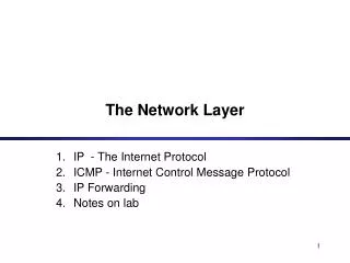
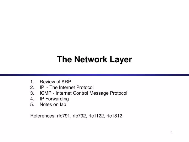
The Network Layer. Review of ARP IP - The Internet Protocol ICMP - Internet Control Message Protocol IP Forwarding Notes on lab References: rfc791, rfc792, rfc1122, rfc1812. Review of ARP. ARP Packet Format. Example. ARP Request from Argon:

E N D
The Network Layer Review of ARP IP - The Internet Protocol ICMP - Internet Control Message Protocol IP Forwarding Notes on lab References: rfc791, rfc792, rfc1122, rfc1812
Example • ARP Request from Argon: Source hardware address: 00:a0:24:71:e4:44Source protocol address: 128.143.137.144Target hardware address: 00:00:00:00:00:00Target protocol address: 128.143.137.1 • ARP Reply from Router137: Source hardware address: 00:e0:f9:23:a8:20 Source protocol address: 128.143.137.1 Target hardware address: 00:a0:24:71:e4:44Target protocol address: 128.143.137.144
ARP Cache • Since sending an ARP request/reply for each IP datagram is inefficient, hosts maintain a cache (ARP Cache) of current entries. The entries expire after a time interval. • Contents of the ARP Cache: (128.143.71.37) at 00:10:4B:C5:D1:15 [ether] on eth0 (128.143.71.36) at 00:B0:D0:E1:17:D5 [ether] on eth0 (128.143.71.35) at 00:B0:D0:DE:70:E6 [ether] on eth0 (128.143.136.90) at 00:05:3C:06:27:35 [ether] on eth1 (128.143.71.34) at 00:B0:D0:E1:17:DB [ether] on eth0 (128.143.71.33) at 00:B0:D0:E1:17:DF [ether] on eth0
Proxy ARP • Proxy ARP: Host or router responds to ARP Request that arrives from one of its connected networks for a host that is on another of its connected networks.
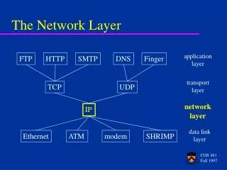
Orientation • IP (Internet Protocol) is a Network Layer Protocol. • IP’s current version is Version 4 (IPv4). It is specified in RFC 791.
IP: The waist of the hourglass • IP is the waist of the hourglass of the Internet protocol architecture • Multiple higher-layer protocols • Multiple lower-layer protocols • Only one protocol at the network layer. • What is the advantage of this architecture? • To avoid the N * M problem
Application protocol • IP is the highest layer protocol which is implemented at both routers and hosts Application protocol Application Application TCP TCP protocol TCP IP IP IP IP IP protocol IP protocol IP protocol Data Data Data Data Data Data Data Data Link Data Link Link Link Link Link Link Link Link Host Router Router Host
IP Service • Delivery service of IP is minimal • IP provides an unreliable connectionless best effort service (also called: “datagram service”). • Unreliable: IP does not make an attempt to recover lost packets • Connectionless:Each packet (“datagram”) is handled independently. IP is not aware that packets between hosts may be sent in a logical sequence • Best effort: IP does not make guarantees on the service (no throughput guarantee, no delay guarantee,…) • Consequences: • Higher layer protocols have to deal with losses or with duplicate packets • Packets may be delivered out-of-order
IP Service • IP supports the following services: • one-to-one (unicast) • one-to-all (broadcast) • one-to-several (multicast) • IP multicast also supports a many-to-many service. • IP multicast requires support of other protocols (IGMP, multicast routing) unicast broadcast multicast
IP Datagram Format • 20 bytes ≤Header Size< 24 x 4 bytes = 64 bytes (maximum 60 bytes) • 20 bytes ≤Total Length< 216 bytes = 65536 bytes (maximum 65535 bytes)
IP Datagram Format • Question: In which order are the bytes of an IP datagram transmitted? • Answer: • Transmission is row by row • For each row: 1. First transmit bits 0-7 2. Then transmit bits 8-15 3. Then transmit bits 16-23 4. Then transmit bits 24-31 • In all of the protocol layers in the TCP/IP suite, any 16- or 32-bit value within the various layer headers (for example, an IP address, a packet length, or a checksum) must be sent and received with its most significant byte first. This iscallednetwork byte order or big endian (big end first) byte ordering. • Note: Many computers (incl. Intel processors) store 32-bit words in little endian format. Others (incl. Motorola processors) use big endian.
Little Endian Stores the low-order byte at the lowest address and the highest order byte in the highest address. Base Address+0 Byte0 Base Address+1 Byte1 Base Address+2 Byte2 Base Address+3 Byte3 Intel processors use this order Big Endian Stores the high-order byte at the lowest address, and the low-order byte at the highest address. Base Address+0 Byte3 Base Address+1 Byte2 Base Address+2 Byte1 Base Address+3 Byte0 Motorola processors use big endian. Big endian vs. little endian • Conventions to store a multi-byte word • Example: a 4 byte Long Integer Byte3 Byte2 Byte1 Byte0
Header fields affected by byte-ordering • Field with length > 8 bits • Total length • Identification • Fragment offset • Checksum • Source / destination address
Fields of the IP Header • Version (4 bits): current version is 4, next version will be 6. • Header length (4 bits): length of IP header, in multiples of 4 bytes • DS/ECN field (1 byte) • This field was previously called as Type-of-Service (TOS) field. The role of this field has been re-defined, but is “backwards compatible” to TOS interpretation • Differentiated Service (DS) (6 bits): • Used to specify service level (currently not supported in the Internet) • Explicit Congestion Notification (ECN) (2 bits): • New feedback mechanism used by TCP for congestion control
Fields of the IP Header • Identification (16 bits): Unique identification of a datagram from a host. Incremented whenever a datagram is transmitted • Flags (3 bits): • First bit always set to 0 • DF bit (Do not fragment) • MF bit (More fragments) Will be explained later Fragmentation • Fragment offset (13 bits)
Fields of the IP Header • Time To Live (TTL) (1 byte): • Specifies longest paths before datagram is dropped • Role of TTL field: Ensure that packet is eventually dropped when a routing loop occurs Used as follows: • Sender sets the value (e.g., 64) • Each router decrements the value by 1 • When the value reaches 0, the datagram is dropped
Fields of the IP Header • Protocol (1 byte): • Specifies the higher-layer protocol. • Used for demultiplexing to higher layers. • Header checksum (2 bytes): A simple 16-bit long checksum which is computed for the header of the datagram.
Fields of the IP Header • Options: • Record Route: each router that processes the packet adds its IP address to the header. • Timestamp: each router that processes the packet adds its IP address and time to the header. • (loose) Source Routing: specifies a list of routers that must be traversed. • (strict) Source Routing: specifies a list of the only routers that can be traversed. • IP options increase routers processing overhead. IPv6 does not have the option field. • Padding: Padding bytes are added to ensure that header ends on a 4-byte boundary
Maximum Transmission Unit • Maximum size of IP datagram is 65535, but the data link layer protocol generally imposes a limit that is much smaller • Example: • Ethernet frames have a maximum payload of 1500 bytes IP datagrams encapsulated in Ethernet frame cannot be longer than 1500 bytes • The limit on the maximum IP datagram size, imposed by the data link protocol is called maximum transmission unit (MTU) • MTUs for various data link protocols: Ethernet: 1500 FDDI: 4352 802.3: 1492 ATM AAL5: 9180 802.5: 4464 PPP: negotiated
IP Fragmentation • What if the size of an IP datagram exceeds the MTU? IP datagram is fragmented into smaller units. • What if the route contains networks with different MTUs? • MTUs:FDDI: 4352Ethernet: 1500 • Fragmentation: • IP router splits the datagram into several datagram • Fragments are reassembled at receiver
Where is Fragmentation done? • Fragmentation can be done at the sender or at intermediate routers • The same datagram can be fragmented several times. • Reassembly of original datagram is only done at destination hosts !!
What’s involved in Fragmentation? • The following fields in the IP header are involved: • Identification • When a datagram is fragmented, the identification is the same in all fragments • Flags • DF bit is set: datagram cannot be fragmented and must be discarded if MTU is too small • MF bit: • 1: this is not the last fragment • 0: last fragment
What’s involved in Fragmentation? • The following fields in the IP header are involved: header total length (in bytes) version DS ECN length D M Identification Fragment offset 0 F F time-to-live (TTL) protocol header checksum • Fragment offset • Offset of the payload of the current fragment in the original datagram in units of 8 bytes • Why? • Because the field is only 13 bits long, while the total length is 16 bits. • Total length • Total length of the current fragment
Example of Fragmentation • A datagram with size 2400 bytes must be fragmented according to an MTU limit of 1000 bytes
Determining the length of fragments • Maximum payload length = 1000 – 20 = 980 bytes • Offset specifies the bytes in multiple of 8 bytes. So the payload must be a multiple of 8 bytes. • 980 - 980 % 8 = 976 (the largest number that is less than 980 and divisible by 8) • The payload for the first fragment is 976 and has bytes 0 ~ 975 of the original IP datagram. The offset is 0. • The payload for the second fragment is 976 and has bytes 976 ~ 1951 of the original IP datagram. The offset is 976 / 8 = 122. • The pay load of the last fragment is 2400 – 976 * 2 = 428 bytes and has bytes 1952 ~ 2400 of the original IP datagram. The offset is 244. • Total length of three fragments: 996 + 996 + 448 = 2440 > 2400 • Why? • Two additional IP headers.
Overview • The IP (Internet Protocol) relies on several other protocols to perform necessary control and routing functions: • Control functions (ICMP) • Multicast signaling (IGMP) • Setting up routing tables (RIP, OSPF, BGP, PIM, …)
Overview • The Internet Control Message Protocol (ICMP) is a helper protocol that supports IP with facility for • Error reporting • Simple queries • ICMP messages are encapsulated as IP datagrams:
ICMP message format 4 byte header: • Type (1 byte): type of ICMP message • Code (1 byte): subtype of ICMP message • Checksum (2 bytes): similar to IP header checksum. Checksum is calculated over entire ICMP message If there is no additional data, there are 4 bytes set to zero. each ICMP messages is at least 8 bytes long
ICMP Query message ICMP query: • Request sent by host to a router or host • Reply sent back to querying host
Example of ICMP Queries Type/Code: Description 8/0 Echo Request 0/0 Echo Reply 13/0 Timestamp Request 14/0 Timestamp Reply 10/0 Router Solicitation 9/0 Router Advertisement The ping command uses Echo Request/ Echo Reply
Example of a Query: Echo Request and Reply • Ping’s are handled directly by the kernel • Each Ping is translated into an ICMP Echo Request • The Ping’ed host responds with an ICMP Echo Reply Hostor Router Host or router ICMP ECHO REQUEST ICMP ECHO REPLY
A system (host or router) asks another system for the current time. Time is measured in milliseconds after midnight UTC (Universal Coordinated Time) of the current day Sender sends a request, receiver responds with reply Example of a Query: ICMP Timestamp TimestampRequest Sender Receiver TimestampReply
ICMP Error message • ICMP error messages report error conditions • Typically sent when a datagram is discarded • Error message is often passed from ICMP to the application program
ICMP Error message • ICMP error messages include the complete IP header and the first 8 bytes of the payload (typically: UDP, TCP)
Example: ICMP Port Unreachable • RFC 792: If, in the destination host, the IP module cannot deliver the datagram because the indicated protocol module or process port is not active, the destination host may send a destination unreachable message to the source host. • Scenario: Request a serviceat a port 80 Client Server No process is waiting at port 80 Port Unreachable
Delivery of an IP datagram • View at the data link layer layer: • Internetwork is a collection of LANs or point-to-point links or switched networks that are connected by routers IP
Delivery of an IP datagram • View at the IP layer: • An IP network is a logical entity with a network number • We represent an IP network as a “cloud” • The IP delivery service takes the view of clouds, and ignores the data link layer view IP
Delivery of IP datagrams • There are two distinct processes to delivering IP datagrams: 1. Forwarding (data plane):How to pass a packet from an input interface to the output interface? 2. Routing (control plane):How to find and setup the routing tables? • Forwarding must be done as fast as possible: • on routers, is often done with support of hardware • on PCs, is done in kernel of the operating system • Routing is less time-critical • On a PC, routing is done as a background process
Routing tables • Each router and each host keeps a routing table which tells the router where to forward an outgoing packet • Main columns: • Destination address: where is the IP datagram going to? • Next hop: how to send the IP datagram? • Interface: what is the output port? • Next hop and interface column can often be summarized as one column • Routing tables are set so that datagrams gets closer to the its destination Routing table of a host or router IP datagrams can be directly delivered (“direct”) or is sent to a router (“R4”)
Delivery with routing tables to:20.2.1.2
Processing of an IP datagram in IP IP router: IP forwarding enabled Host: IP forwarding disabled
Processing of an IP datagram in IP • Processing of IP datagrams is very similar on an IP router and a host • Main difference: “IP forwarding” is enabled on router and disabled on host • IP forwarding enabled if a datagram is received, but it is not for the local system, the datagram will be sent to a different system • IP forwarding disabled if a datagram is received, but it is not for the local system, the datagram will be dropped
Processing of an IP datagram at a router • IP header validation • Process options in IP header • Parsing the destination IP address • Routing table lookup • Decrement TTL • Perform fragmentation (if necessary) • Calculate checksum • Transmit to next hop • Send ICMP packet (if necessary) Receivean IP datagram