Download
1 / 14
140 likes | 145 Views
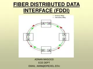
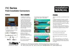
Fiber Cable/Spectrograph Interface: The Slit-Plate. Slit-Plate models are coming together. Who will fab and assemble the parts, and how, will be integral to further design. Models and drawing are being worked up to address these issues.

E N D
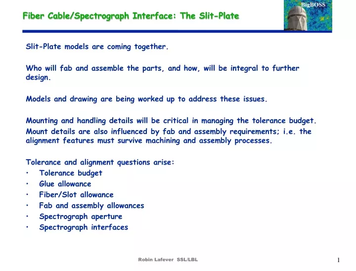
Fiber Cable/Spectrograph Interface: The Slit-Plate Slit-Plate models are coming together. Who will fab and assemble the parts, and how, will be integral to further design. Models and drawing are being worked up to address these issues. Mounting and handling details will be critical in managing the tolerance budget. Mount details are also influenced by fab and assembly requirements; i.e. the alignment features must survive machining and assembly processes. Tolerance and alignment questions arise: • Tolerance budget • Glue allowance • Fiber/Slot allowance • Fab and assembly allowances • Spectrograph aperture • Spectrograph interfaces Robin Lafever SSL/LBL
Slit-Plate Module 128 Fibers 4 x 32 fiber Connectors Cable Clamp Cover Plate 32 fiber Connector Fiber Array (128 fibers) Furcation tube, 4.5 mm dia. Fiber array Pigtail Each array contains 32 fibers Slit-Plate Body Lenslet Robin Lafever SSL/LBL
Slit-Plate Module 128 Fibers 4 x 32 fiber Connectors Generic 128 fiber Module (no mounting features) Simplified fab and assembly: Lenslet Cover, Body, and Pigtail are fabbed separately. 2. Fibers are glued into slots, sandwiched between Cover and Body And staked at this surface. Pigtails are clamped. 3. Surfaces are ground and polished 4. Lenslet bonded on. Robin Lafever SSL/LBL
4 Modules, 512 Fibers, at the Spectrograph Approximate alignment using 4 x 128 fiber Modules Robin Lafever SSL/LBL
4 Modules, 512 Fibers, at the Spectrograph In the current Spectrograph design, these 2 surfaces are available for mounting and alignment features Robin Lafever SSL/LBL
4 Modules, 512 Fibers, at the Spectrograph A crude envelope, carrying the slit-plates, mated to the Spectrograph aperture Robin Lafever SSL/LBL
Adapter envelope A crude envelope, carrying the slit-plates, mated to the Spectrograph aperture No space in here for the “Lossy Fiber” assembly ! Robin Lafever SSL/LBL
Adapter envelope At present, these 2 faces are available for alignment features Surface defines the Aperture slot Conspicuously missing, is the “Lossy Fiber Assembly”. No room. Needs rethinking. ( This image was worked up to illustrate a misfit between the Spectrograph model and the Slit-Plate model, based on place-holder dimensions. This has since been resolved. New models are in the works. ) Robin Lafever SSL/LBL
128 fiber Module x 4, 512 fibers 512 fiber Slit-Plate Assembly With base-plate. Robin Lafever SSL/LBL
128 fiber Module x 4, 512 fibers 512 fiber Slit-Plate Assembly With base-plate. This is not kinematic. Pins set the azimuthal alignment, Ground pads set the in-plane alignment. Ground stops set the radial alignment. Robin Lafever SSL/LBL
100 fiber module x 5, 500 fibers 500 fiber Slit-Plate Assembly Robin Lafever SSL/LBL
100 fiber module x 5, 500 fibers Similar Pin-Pad treatment. Robin Lafever SSL/LBL
Next It’s time to start considering the Spectrograph integration scheme and moving toward an Interface Document. At present, confirmation of a few critical dimensions will be adequate but more details will be needed soon. New models are underway to match the current Spectrograph geometry. Drawings will follow soon, to be sent to fab candidates to get real feed-back. Now, however, I am soliciting input on mounting and alignment schemes. Candidate methods, at the moment, include: Bolts, or Bonding, or Magnets. Rework to the new numbers may open up some space at the Spectrograph aperture to accommodate the “Lossy Fiber Assembly”. Maybe not. It needs some more thinking. Robin Lafever SSL/LBL