Download
1 / 11
110 likes | 231 Views
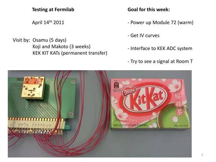
Testing at Fermilab April 14 th 2011. Goal for this week: - Power up Module 72 (warm) - Get IV curves - Interface to KEK ADC system - Try to see a signal at Room T. Visit by: Osamu (5 days) Koji and Makoto (3 weeks) KEK KIT KATs (permanent transfer).

E N D
Testing at Fermilab April 14th 2011 Goal for this week: - Power up Module 72 (warm) - Get IV curves - Interface to KEK ADC system - Try to see a signal at Room T Visit by: Osamu (5 days) Koji and Makoto (3 weeks) KEK KIT KATs (permanent transfer)
Quiet 1 Module 72 All LNA’s have individual Gate Control Summary All Active Devices on Module 72 appear to be alive at room T Success: We see the internal noise signal We see signal from Gunn Oscillator Goal for Next Week: - Move system to Cryostat - Do cool down
KEK 64-channel ADC system Bias Board and MAB and Gunn Diode KEK Preamp
Leg A Drain Current versus Gate Voltage Drain Voltage for all LNA’s = 250 mV We did NOT do I-V curve for V-drain = 750 mV (afraid of pushing too much drain current) LNA1 LNA3 LNA2
Leg B Drain Current versus Gate Voltage Drain Voltage for all LNA’s = 250 mV We did NOT do I-V curve for V-drain = 750 mV (afraid of pushing too much drain current) LNA1 LNA3 LNA2
Warm IV curve of U2 Detector Diode We found that the Detector Diode Polarity in module 72 is OPPOSITE of what we expect. We adapted by reversing our low voltage lines. Result shown AFTER reversing voltage lines
Module is ALIVE: Receiver Noise is seen by KEK ADC system Total Power signal x 100 seen by KEK ADC system Phase switch Diode PA1 is turned ON and OFF
Toggling Phase Switch Power All Phase Switch Diodes are alive Note: Plotted is total power seen by KEK ADC x 100
Inject W-band power (from Gunn oscillator) into module, modulated at 1 Hz
Inject W-band power (from Gunn oscillator) into module, modulated at 1 Hz Zoomed in time