Download
1 / 52
660 likes | 932 Views
Ch 5 . Logic Design with MSI Components. VHDL.

E N D
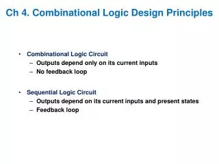
VHDL • The U.S. Department of Defense (DoD) supported the development of VHDL (VHSIC hardware description language) as part of the VHSIC (very high-speed IC) program in the early 1980s. The companies in the VHSIC program found they needed something more than schematic entry to describe large ASICs, and proposed the creation of a hardware description language. VHDL was then handed over to the Institute of Electrical and Electronics Engineers (IEEE) in order to develop and approve the IEEE Standard 1076-1987. 1 As part of its standardization process the DoD has specified the use of VHDL as the documentation, simulation, and verification medium for ASICs (MIL-STD-454). Partly for this reason VHDL has gained rapid acceptance, initially for description and documentation, and then for design entry, simulation, and synthesis as well. • The first revision of the 1076 standard was approved in 1993. References to the VHDL Language Reference Manual (LRM) in this chapter--[VHDL 87LRM2.1, 93LRM2.2] for example--point to the 1987 and 1993 versions of the LRM [IEEE, 1076-1987 and 1076-1993]. The prefixes 87 and 93 are omitted if the references are the same in both editions. Technically 1076-1987 (known as VHDL-87) is now obsolete and replaced by 1076-1993 (known as VHDL-93). Except for code that is marked 'VHDL-93 only' the examples in this chapter can be analyzed (the VHDL word for "compiled") and simulated using both VHDL-87 and VHDL-93 systems.
Logic Gates and Symbols And Or Not a a F F F a b b F = a b F = a + b F = !a
Logic Equation Representation: Sum-of-Products (SOP) • SOP form: • A collection of ANDed variables are Ored together. • Example: F = !A!B + AB Also called XNOR
Example of SOP • Example: A three-input majority function • The function is true when more than half of its inputs are true F =?
Example of SOP • Example: A three-input majority function • The function is true when more than half of its inputs are true F = !ABC+A!BC+AB!C+ABC
Digital Components • High level digital designs are usually made using collections of logic gates. Such collection of gates are referred as components. • Multiplexer and Decoder are commonly used digital components. • Levels of integration • SSI (Small Scale Integration) 10-100 components per chip • MSI (Medium Scale Integration) 100-1,000 components per chip • LSI (Large Scale Integration) 1000-10,000 components per chip • VLSI (Very Large Scale Integration) – Higher • ULSI (Ultra Large Scale Integration) – Higher, higher!
An 8-bit multiplexer • entity Mux8 is • generic (TPD : TIME := 1 ns); • port (A, B : in BIT_VECTOR (7 downto 0); • Sel : in BIT := '0'; Y : out BIT_VECTOR (7 downto 0)); • end; • architecture Behave of Mux8 is • Begin • Y <= A after TPD when Sel = '1' else B after TPD; • end; Eight 2:1 MUXs with single select input. Timing: TPD (input to Y) = 1 ns
Sum =A’BC’ + AB’C’ + A’B’C + ABC Carry-out = ABC’ + A’BC + AB’C + ABC
A full adder • Entity Full_Adder is • generic (TS : TIME := 0.11 ns; TC : TIME := 0.1 ns); • port (X, Y, Cin: in BIT; Cout, Sum: out BIT); • end Full_Adder; • architecture Behave of Full_Adder is • begin Sum <= X xor Y xor Cin after TS; • Cout <= (X and Y) or (X and Cin) or (Y and Cin) after TC; • end; • Timing: • TS (Input to Sum) = 0.1 1 ns • TC (Input to Cout) = 0.1 ns
An 8-bit ripple-carry adder • entity Adder8 is • port (A, B: in BIT_VECTOR(7 downto 0); • Cin: in BIT; Cout: out BIT; • Sum: out BIT_VECTOR(7 downto 0)); • end Adder8; • architecture Structure of Adder8 is • component Full_Adder • port (X, Y, Cin: in BIT; Cout, Sum: out BIT); • end component; • signal C: BIT_VECTOR(7 downto 0); • begin • Stages: for i in 7 downto 0 generate • LowBit: if i = 0 generate • FA:Full_Adder port map (A(0),B(0),Cin,C(0),Sum(0)); • end generate; • OtherBits: if i /= 0 generate • FA:Full_Adder port map (A(i),B(i),C(i-1),C(i),Sum(i)); • end generate; • end generate; • Cout <= C(7); • end;
The single input line into each AND gate represents 6 input lines The single input line into each OR gate represents 8 lines Darkened circles are placed at crosspoints to indicate connections are made
When A,B,C all changed from 0 to 1, there will Be a glitch.
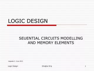
Flip-Flop • A Flip-flop is an arrangement of logic gates that maintains a stable output even after the inputs are made inactive. • A flip flop can be used to store a single bit of information. • A S-R flip flop holds a single bit of information and serve as an elementary memory cell. • In order to achieve synchronization in a controlled fashion, a clock signal is provided. Every state-dependent circuit synchronizes itself by accepting inputs only at discrete times.
Truth Table for Mod-4 Counter Note that S1/S0 are identical to Q1/Q0
Finite State Machine Z2 X1 4X5 PLA Z1 X0 Z0 Q D S0 CLK Q D S1