Download
1 / 26
270 likes | 357 Views
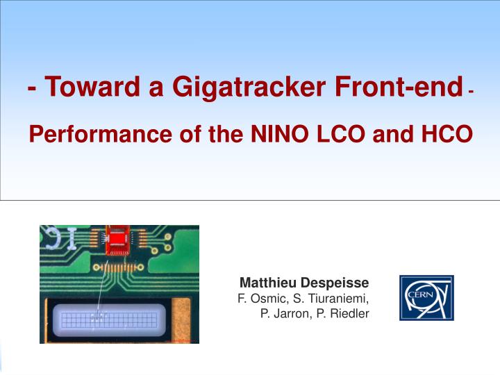
- Toward a Gigatracker Front-end - Performance of the NINO LCO and HCO. Matthieu Despeisse F. Osmic, S. Tiuraniemi, P. Jarron, P. Riedler. Electrical characterizations of NINO LCO. Laser Measurements :Data analysis w. induced signal calculations. NINO LCO + pre-amp.

E N D
- Toward a Gigatracker Front-end - Performance of the NINO LCO and HCO Matthieu Despeisse F. Osmic, S. Tiuraniemi, P. Jarron, P. Riedler
Electrical characterizations of NINO LCO Laser Measurements :Data analysis w. induced signal calculations NINO LCO + pre-amp Characterization of the NINO HCO OUTLINE
The 130 nm NINO test-ASIC Integrated electronics : - LCO, 3 channels - HCO NINO_v13: 1.4 mm × 1 mm
NINO LCO calibration • LCO optimized for 200 fF input capacitance • (Higher Cin degrades jitter + minimum threshold) Calibration via a 1 pF injection capacitance OUTSIDE CHIP Calibration via a 100 fF injection capacitance IN CHIP corresponds to the expected performance in a hybrid pixel configuration of LCO estimates what to expect from external measurements on this chip Laser Measurements on Silicon sensor pixel Expected LCO timing precision for hybrid detector
NINO LCO calibration CALIBRATION w/ 100 fF injection capacitance 1 ns Threshold @ 1.5 fC
NINO LCO calibration CALIBRATION w/ 100 fF injection capacitance Expected LCO global timing precision
NINO LCO calibration CALIBRATION w/ 1 pF injection capacitance External TESTS 1 ns
NINO LCO calibration CALIBRATION w/ 1 pF injection capacitance External TESTS Strong degradation of measured jitter compared to the 100 fF tests
NINO LCO calibration - Conclusion • LCO designed for 200 fF input capacitance • Higher Cin degrades jitter + minimum threshold CALIBRATION w/ 1 pF injection capacitance External TESTS CALIBRATION w/ 100 fF injection capacitance Laser Measurements on Silicon sensor pixel Expected LCO global timing precision in the Gigatracker application ? Simulations Data analysis
Electrical characterizations of NINO LCO Laser Measurements : Data analysis w. induced signal calculations NINO LCO + pre-amp Characterization of the NINO HCO OUTLINE
Test set-up – Fadmar, Sakari Silicon detector: 300 µm × 300 µm pixel, 200 µm thick sensor Wire bond connection to a LCO channel 1060 nm pulsed Laser tests Laser calibration – position done / Fadmar, Sakari 1 ns
Induced signal – simple calculations Simple calculations based on 200 V detector bias + infinite parallel plate approximation For a simultaneous generation of e-/h+ pairs equally distributed in the sensor thickness (MIP) Ideal shape
Induced signal – simple calculations Simple calculations based on 200 V detector bias + infinite parallel plate approximation Taking into account the laser pulse shape
Induced signal – simple calculations Simple calculations based on 200 V detector bias + infinite parallel plate approximation Taking into account the laser pulse shape
1 ns Tests results Calculated signals + 1.2 pF total Cin give good fitting measurements 1 ns Simulations w. calculated signals
NINO LCO SIMULATIONS w. calculated signals Calculated signals + 1.2 pF total Cin give good fitting Precise Jitter estimation from simulations measurements measurements Simulations w. calculated signals Simulations w. calculated signals
NINO LCO SIMULATIONS w. calculated signals CAPACITANCE INFLUENCE sim. 1.2 pF measurements sim. 0.7 pF measurements sim. 0.7 pF sim. 1.2 pF sim. 0.3 pF sim. 0.3 pF
NINO LCO SIMULATIONS w. calculated signals CAPACITANCE INFLUENCE Reducing the capa. reduces the pulse width and so the time walk variations 1 ns Points simulated w. similar input signals
Measurements w. 100 fF injection NINO LCO SIMULATIONS w. calculated signals What we expect w. Ideal shape signals Jitter estimation for the LCO connected via bump bonding to the sensor: < 180 ps for Q > 1.5 fC
Electrical characterizations of NINO LCO Laser Measurements :Data analysis w. induced signal calculations NINO LCO + pre-amp Characterization of the NINO HCO OUTLINE
Use of additionnal pre-amp for the Gigatracker pixel front end NINO LCO SIMULATIONS w. pre-amp Pre-amp Under optimization Ideal currents 1, 2, 3fC LCO inputs LCO outputs
Jitter performance (simulations) NINO LCO SIMULATIONS w. calculated signals Th @ 0.5 fC Th @ 1 fC Pre-amp Under optimization Jitter < 150 ps for charges >= 0.8 fC Th @ 0.7 fC
Electrical characterizations of NINO LCO Laser Measurements :Data analysis w. induced signal calculations Characterization of the NINO HCO NINO LCO + pre-amp OUTLINE
NINO HCO HCO circuit optimized for few pF input capacitance Tests via a 1 pF capacitance OUTSIDE CHIP, for a Rin ~ 75 Ω – Power ~ 4.5 mW / channel Minimum charge @ 6 fC Minimum charge @ 10 fC Minimum charge @ 12.5 fC
NINO HCO HCO circuit optimized for few pF input capacitance Tests via a 1 pF capacitance OUTSIDE CHIP, for a Rin ~ 75 Ω – Power ~ 4.5 mW / channel NB: Simulation technique for the jitter shows good results on HCO too.
NINO LCO measurements - simulations Pre-amp + LCO - simulations HCO possible candidate for end of column receiver CONCLUSIONS • Showed that we can reach for a hybrid detector : • min. detectable charge of 1.5 fC @ 200 ps rms • jitter < 150 ps for charges > 2 fC • Showed that we can reach for a hybrid detector : • min. detectable charge of 0.5 fC @ 250 ps rms • jitter < 150 ps for charges > 0.8 fC Measurements and simulations show < 20 ps rms jitter for fast input signals w. charges > 10 fC