Download
1 / 50
500 likes | 630 Views
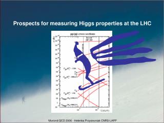
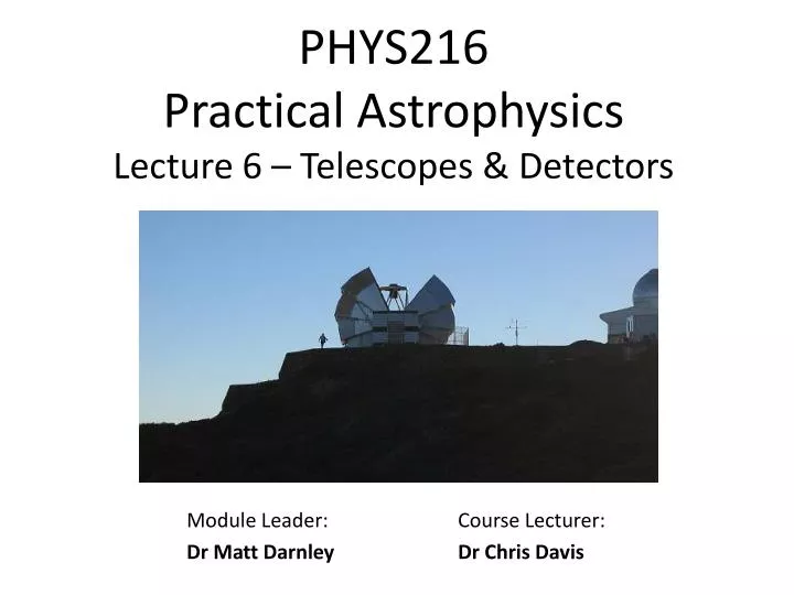
PHYS216 Practical Astrophysics Lecture 6 – Telescopes & Detectors. Module Leader: Dr Matt Darnley. Course Lecturer : Dr Chris Davis. Wavelength Coverage. Detecting photons at different wavelengths requires very different technologies. UV. IR.

E N D
PHYS216 Practical AstrophysicsLecture 6 – Telescopes & Detectors Module Leader: Dr Matt Darnley Course Lecturer: Dr Chris Davis
Wavelength Coverage Detecting photons at different wavelengths requires very different technologies.
UV IR
Radio, l ≈ 1 m (Left) The 100-m Green Bank Radio Telescope (GBT), NRAO Green Bank, West Virginia. (Right) Artists' impression of part of the Square Kilometer Array (SKA).
Sub-millimetre, l ≈ 1 mm (Left) The 15-m James Clerk Maxwell Telescope (JCMT), Mauna Kea, Hawaii. (Right) The 3.5m Herschel Space Observatory (artists impression).
Mid- to Far-Infrared, l ≈ 0.01-0.1 mm (Left) The 0.85-m Spitzer Space Telescope. (Right) The Stratospheric Observatory for Infrared Astronomy (SOFIA) and its 2.5m telescope.
SOFIA – IR Astronomy from a Plane! http://www.sofia.usra.edu/
SOFIA Super-TIGER Astronomy from a Plane! • Quick, low cost (few million $) access to high altitudes EBEX BLAST
Near-Infrared, l ≈ 1-5 mm (Left) The 3.8m UK Infrared Telescope (UKIRT), Hawaii. (Right) Model of the James Webb Space Telescope (JWST, optical to mid-IR).
JWST Deployment at L2i.e. when its 1.5 million km from Earth
Optical, l ≈ 0.4-0.8 mm (Left) The four 8.2-m telescopes of the Very Large Telescope (VLT), Chile. (Right) The 2-m fully robotic Liverpool Telescope (LT), La Palma.
Utraviolet, l ≈ 0.1 mm (Left) The 0.5m Galaxy Evolution Explorer (GALEX). (Right) The 2.4m Hubble Space Telescope (HST, UV to near-IR).
X-ray, l ≈ 10 nm (Left) The X-ray Multi-Mirror Mission (XMM) Newton Telescope. (Right) The Chandra X-ray Observatory,
Gamma-ray, l ≤ 1 nm (Left) The Fermi Gamma-ray Space Telescope. (Right) Swift (Gamma-ray, X-ray, UV and optical).
High-energy and Far-IRastronomy from Balloons! BLAST (left) and EBEX (above) both observe in the Far-IR. Many balloons are launched from Antarctica, where water vapour levels are very low…
Why use telescopes? • Light collection power • Diameter of eye/pupil - a few millimetres • Diameter of large ground based optical telescopes – 10 m. • Integration • Eye: sampling frequency 25 Hz • Telescope: hours; days or longer from space. • Resolving power – • Telescopes strive to be seeing-limited. • The eye, due to its small aperture, is diffraction-limited, giving very low resolution.
Diffraction-limited vs. Seeing-limited Diffraction limit: fundamental maximum to theresolution of any optical system. Diffraction limited: • If angular resolution (the angular separation between two objects, or the “width” of a star measured at half the intensity) is as good as the instrument's theoretical limit. However, most telescopes are Seeing limited… .
The Rayleigh (or Diffraction) Limit Rayleigh criterion: sin q = 1.22 l/ D. q - angular resolution D - size of aperture • - wavelength (550 nm, say, for optical) Q. The Gemini Telescope has an 8 meter diameter mirror, and it operates in the optical (550 nm) and the infrared (5 mm). At which wavelength would you expect to get better spatial resolution? Image: VikDhillon Q. The Hubble Space Telescope has only a 2.4 m aperture (primary mirror). What’s the best resolution you can expect from HST in the optical, and how does it compare to Gemini?
What affects the “Seeing” Blurring or twinkling of stars by the atmosphere - Seeing. Seeing caused by Refraction which varies with density and temperature.
Magnification & Field of View Magnifying power = Focal length of objective, fo Focal length of eyepiece, fe Focal ratio of objective (or mirror) = Focal length of lens, fo Diameter of lens, D f-ratio is also indicative of the maximum field-of-view available through the telescope system (primary/secondary mirror)
Magnification & Field of View Primary mirror f-ratio = f/3 Primary mirror D = 2.0 m Focal length fp = 6.0 m Therefore, the mirror focuses light to a point 6 m above the primary. BUT - the secondary mirror changes the overall f-ratio of the telescope! Effective (overall) f-ratio = f/10 Primary mirror D = 2.0 m Effective focal length fp≈ 20 m Approx. distance from primary to the Cassegrain instruments
Magnification Unfortunately a small fuzzy blob when magnified just becomes a largefuzzy blob. Magnified objects are also fainter, since you spread the light out over more pixels.
Reflectors vs Refractors The first astronomical telescopes – Refractors. Galileo (1564-1642) didn’t invent the telescope: - Dutch spectacle makers did this! And he wasn’t even the first to use one: - Thomas Harriot drew Earth’s moon in 1609 Refractors - Pros: • Rugged – stable optical alignment • Inner glass surfaces sealed in; keep clean • Air current and temperature effects minimised Refractors - Cons: • Lenses must be supported around the edge. • Larger lenses are heavy, and expensive! • Suffer from various forms of aberration
Aberrations • Spherical aberration : • Spherically lens curved focal plane with blurred off-axis images.
Aberrations • Coma (left) and Astigmatism (right) - Off-axis images further distorted.. Astigmatism: Rays in perpendicular planes have different focii Coma: Rays not parallel with the axis are spread out…
Aberrations • Chromatic aberration: • - Refractive index is a function of wavelength • - Different foci for different wavelengths distorted colour “halos”. • Reduced by a long focal length (thin lenses) or compound lenses made of different materials.
Aberrations Instrument Spot diagrams - used to determine how distorted images will be. Spot diagrams for the Subaru/CISCO instrument, at different wavelengths and off-axis angles. Aberrations can be reduced by using multiple-lens systems.
HST Spherical Aberrations • HST 2.4m primary mirror: • At the time, the most precisely ground mirror ever produced. • …but suffered from catastrophic spherical aberration • Problem corrected three years after launch with additional optics; installed during the first servicing mission. (Left) M100 before corrective optics. (Right) M100 after corrective optics.
Reflectors vs. Refractors • Most modern astronomical telescopes: • Reflectors • Largest single-piece optical telescope - the Large Binocular Telescope : 2x 8.4 m mirrors. • Segmented mirrors – the future..? • Reflectors - Pros: • No chromatic aberration. • By using paraboloidal shapes, spherical aberration can be removed. • Easier to manufacture • Can be supported from behind • Reflectors – Cons: • Open to the elements • Coma and astigmatism still a problem Above - LBT 8.4m mirror. Below – Keck 10m mirror
Reflectors Most large telescopes are reflectors (though their instruments may still use lenses) Naysmith Focus Instruments are usually mounted at the Cassegrain, Prime or Naysmith Focus Gemini 8 meter Telescope
Telescope Mountings - Equatorial Two main types of telescope mounting: Equatorial and Altitude-Azimuth. • Equatorial telescopes: • Designed for a particular latitude • declination axis points to the north celestial pole. • Only needs to track stars through one axis. • Simple design, but heavy. Model of the UK Infrared Telescope. The red “tube” is an instrument sitting on the primary mirror!
Telescope Mountings – Alt-Az Two main types of telescope mounting: Equatorial and Altitude-Azimuth. • Alt-Az telescopes: • Simple “up-down" and “revolving" mount. • Must track through both the Alt and Az axis, PLUS Cassegrain de-rotation. • Tracking can be tricky • Zenith “blind spot" due to near-infinite de-rotator speeds. • Simple engineering • Used on most modern large telescopes. Computer model of the proposed Thirty Meter Telescope (TMT)
Detectors – the Basics Quantum efficiency (QE): the probability that a photon with a given energy (i.e. at a specific wavelength) will be detected. If only 1 in 10 photons are detected, QE = 10%. A detector with a QE of 40% will need twice the exposure time of a detector with a QE of 80% to collect the same number of photons. QE is a function of wavelength - need different detectors for different wavelength regimes
The Eye Two types of detectors (retinal receptor cells) - rods and cones Rods - detect monochrome only - they contain rhodopsin, a complex protein pigment in layers 20 nm thick. When a photon is absorbed, a piece of the protein breaks off leaving behind a colourless substance (opsin). An associated change in potential causes an electrical signal in the optic nerve. Peak sensitivity of rods occurs at wavelengths around 500 nm • Cones - 3 types sensitive to 3 distinct wavelength ranges: • Blue - narrow, peak near 419 nm • Green - broader, peak near 531 nm • Red - also broad, peak near 558 nm.
Dark Adaptation • Wavelengths shorter than 315 nm (UV) - absorbed by the cornea. • Wavelengths shorter than 1000 nm (near-IR) - retinal sensitivity sometimes extends to 1000-1050 nm. • In the dark: • rods dominate since their sensitivity is about 100 times greater than for cones - at night we rely on monochrome vision. • rhodopsin (in rods) reforms on a time-scale of 30 mins. Red light less likely to reduce dark adaption.
Naked Eye Astronomy The Rayleigh limit* of the fully open iris (5-7 mm) is ≈ 25” but the receptor cell spacing is ≈ 1’-2’. Latter is the maximum resolution of the eye. The faintest stars visible to naked eye : mV≈ 6 (remember Hipparchos?) • Q. Can you resolve (distinguish) Maia from Alcyone with the naked eye? • Maia (V = 3.9m) • RA: 3h 45m 50.0s Dec: 24o 22’ 10” • Alcyone (V = 2.9m) • RA: 3h 47m 29.0s Dec: 24o 06’ 20” David Malin/AAT *NB: Rayleigh criterion relates angular resolution, q , to the size of the aperture, D and the wavelength of the observation, l: sin q = 1.22 l/ D.
Photographic Plates • Photons cause chemical changes in photographic emulsions. • Advantages: Large area and relatively cheap. • Limitations: Non-linear response; scattering degrades resolution; QE < 10% • Scanning machines used to digitize photographic plates. Photo courtesy ESO DSS images from Palomar Observatory (North) and the UK Schmidt Telescope (South)
Photographic Plates Left: Hubble at the Palomar Schmidt; Right: His 1926 plate of M33 with at least one Classical Nova marked Rarely used today, though vast century-old archives still exist...
CCDs (Charge-Coupled Devices) Photons incident on a semiconductor (doped silicon) produce electron-hole pairs. The electrons accumulate in potential wells produced by attached electrodes until read out by “charge coupling” the electrodes. Charge coupling: cycling the voltages on each electrode in sequence, to shuffle the charge along to an output electrode (below-right). The resulting analogue signal is then amplified and digitised. Note: IR photons with l > 1.1 mm have insufficient energy Electrons collect in potential wells produced by the gate electrodes (G); charge shifted to the right by shifting the applied voltage on each gate. Above: photon excites electron from valence to conduction band -> electron-hole pair.
CCDs (Charge-Coupled Devices) • CCDs first used by astronomers in the mid-1980s • - More efficientand more sensitive than photographic film. • BUT … Science grade optical CCDs are extremely expensive Left - The array of four 2kx4k pixel detectors of the INT WFC (plus finder chip). Right - WFC3 being installed on HST. Note the size of the camera compared to CCDs!
CCDs – Quantum Efficiency Efficiency of conversion of photons into electrons - the Quantum Efficiency: - around 75-90% in a CCD (cf 2% for photographic lm). BUT - QE does change with wavelength and temperature. Standard optical CCDs - sensitive to wavelength range l= 400 - 1000 nm. LEFT: The QE response of the detectors used in the Andor cameras at the LT when cooled to -100oC. Photons falling onto the “front” of the detector must traverse the gate electrodes; the gate electrodes can reflect or absorb photons, thereby reducing the QE. It may therefore be desirable to illuminate the back of the CCD.
CCDs - Cryogenics • Scientific grade CCDs must be cooled with: • Liquid nitrogen (T~70K) or liquid helium (T~ 4K) • Use closed-cycle-cooler (closed cooling circuit) in a cryostat or dewar. • Cooling reduces Dark Current (signal per second) from thermal electrons in the CCD. The associated noise is proportional to √dark current. RIGHT: The IO:O cryostat – the gold cylinder - mounted on the Liverpool Telescope.
CCDs - Cryogenics Closed-Cycle Cooling system used at the LT to cool the detectors in IO and FRODOspec. CryoTiger Compressor RETURN (30 psi) Air flow Cold Head on the instrument Heat Exchanger Gas Compressor SUPPLY (300 psi) Gate valve to vacuum pump • Cryotiger pumps compressed PT13 liquid into the cold-head • It expands adiabatically, extracting heat from the heat strap • Warm PT13gas returns to the cryotiger where it is passes through the compressor and heat exchanger • Note that everything inside the coldhead is kept in a vacuum! Heat Shield Cold Plate Getter Copper heat strap
CCDs - Cryogenics “Amateur" astronomical CCD cameras use thermo-electric cooling, via the Peltier effect, to cool the detectors by typically20 – 30o. Uses Thermo-electric cooling (conversion of temperature differences to voltage) to extract heat energy from the system. • Hot and Cold plate connected by doped semi-conductive thermo-couples • When DC voltage applied: hot plate heats up, cold plate cools down! • Advantages of this cooling device: • lack of moving parts • does not involve cryogenic liquids
CCDs – Gain & Bias GAIN: - the number of “counts" does NOT equal the number of photons detected. Gain = electrons per pixel / counts per pixel In the Analogue-to-Digital Converter (ADC) 16-bit unsigned integers gives a range from 0 [216 – 1] or 0 65535). This number probably not sufficient for the maximum number of electrons that can be stored in a given pixel. A gain of 8 means that each count is equivalent to 8 photoelectrons • BIAS: • a small voltage applied to raise the output signal above zero. • - the signal + random noise is always positive, since the ADC can’t deal with negative analogue input!
CCDs – Cosmic Rays Cosmic rays produce free electrons in the semiconductor creating bright pixels or `spikes’…. Before cleaning… After IO:O images of NGC 7479, before and after cosmics have been removed