Download
1 / 12
310 likes | 968 Views
Dynamic Mode Decomposition (DMD) application to premixed Low Swirl Injector flames.<br><br>68th Annual Meeting of the APS Division of Fluid Dynamics<br>Volume 60, Number 21<br><br>

E N D
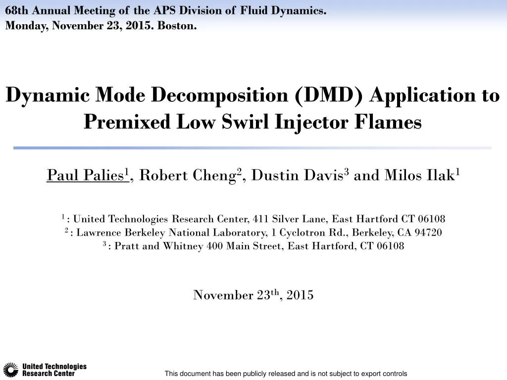
68th Annual Meeting of the APS Division of Fluid Dynamics. Monday, November 23, 2015. Boston. Dynamic Mode Decomposition (DMD) Application to Premixed Low Swirl Injector Flames Paul Palies1, Robert Cheng2, Dustin Davis3 and Milos Ilak1 1 : United Technologies Research Center, 411 Silver Lane, East Hartford CT 06108 2 : Lawrence Berkeley National Laboratory, 1 Cyclotron Rd., Berkeley, CA 94720 3 : Pratt and Whitney 400 Main Street, East Hartford, CT 06108 November 23th, 2015 This document has been publicly released and is not subject to export controls
DMD for combustion dynamics DMD complement existing method to identify mechanisms of instability FLOW FIELD COMBUSTION Combustion dynamics resonant loop DMD ACOUSTICS DMD reveals information in experimental or simulation data in complement to other technics DMD describes the dynamics of the data (how the flame evolves in time and space) DMD identifies flow structures and wave patterns Impact of DMD for combustion dynamics This document has been publicly released and is not subject to export controls 2
DMD Algorithm* implemented and verification DMD algorithm validated on prescribed known signals respectively (V2 is V1 shifted by one time step) Snapshot matrices V1 and V2 contain snapshots from 1 to N and 2 to N+1, H Mode amplitude V W V U Uy log( U Singular Value Decomposition Assume a linear mapping A A can be approximated by S 1 AV AU y S 1 2 ~ S 1 H H U V W 2 DMD Modes ɸi Eigenvectors yi Eigenvalues λi i i y / ) ~ [rad/s] i i i t i i Note that the application of the algorithm does not require underlying linear dynamics in the data. Mode Growth Rate Input signal for verification: oscillating 2D amplified standing wave Spatial mode distribution i f 30 1700 rad/s Growth rate Hz Frequency * Peter J. Schmid. Dynamic mode decomposition of numerical and experimental data. Journal of Fluid Mechanics 2010. Vol.656, pages 5-28. This document has been publicly released and is not subject to export controls 3
Experimental Setup and Data: Low Swirl Injector (LSI) Fully premixed swirling flames analyzed at three equivalence ratios Data generated as part of joint LBNL and UTRC work optical access for flame imaging flame image snapshot pressure signal Low swirl imparted to premixed reactants upstream of combustion chamber Fully premixed flame (H2-CH4-Air mixture) 3 regimes (stable, transient, and limit cycle) corresponding to three equivalence ratios Flame images synchronized with pressure probe measurement Pressure Probe injector Self-induced unstable behaviors of CH4 and H2/CH4 flames in a model combustor with a low- swirl injector. Therkelsen, P ., Enrique Portillo, J., Littlejohn, D. , Martin, S. and Cheng, R. Combustion and Flame 160 (2013) 307–321 This document has been publicly released and is not subject to export controls 4
Selection of the data set for DMD analysis Data selected to analyze stable, transient and limit cycle oscillations. ɸ=0.30 Stable regime Three different equivalence ratios Transient regime ɸ=0.38 Limit cycle regime ɸ=0.40 f = 328 Hz f = 335 Hz Pressure probe data used to determine the regime of oscillation This document has been publicly released and is not subject to export controls 5
Unsteady Combustion Data Flame images pixel intensity summed to form Unsteady Heat Release (UHR) signals Limit cycle regime Transient regime Stable regime Flame image snapshots ɸ=0.30 ɸ=0.38 ɸ=0.40 Flame front location changes due to equivalence ratio difference This document has been publicly released and is not subject to export controls 6
DMD Flame Data Results: frequency content Peak frequency in DMD spectrum in agreement with pressure measurements Stable regime Transient regime Limit cycle regime Peak: f = 321 Hz Peak: f = 340 Hz fexp = 335 Hz fexp = 328 Hz Amplitude Amplitude This document has been publicly released and is not subject to export controls 7
DMD results: growth rates comparison Growth rate in transient regime identified by DMD [rad/s] Stable regime No amplified mode ωi < 0 Growth rate trend captured across the three analyzed regimes [rad/s] Transient regime Peak: f = 321 Hz ωi = 5.15 rad/s [rad/s] Limit cycle regime Peak: f = 340 Hz ωi = -1.3 rad/s 8 This document has been publicly released and is not subject to export controls
DMD results: spatial modes Comparison of spatial mode distribution for each regime (0 Hz and ~340 Hz modes) Limit cycle regime Transient regime Stable regime MEAN at 0 Hz Mean flame front location changes due to equivalence ratio difference MODE ~340 Hz Spatial mode associated to transition to instability This document has been publicly released and is not subject to export controls Spatial mode associated to noise Spatial mode associated to instability 9
Analysis of the Results Combustion dynamics features wave pattern identification Transient Limit cycle λ/2 λ/2 u = λ f Frequency f 320 Hz 336 Hz u 12.8 m/s 13.4 m/s λ wavelength 40 mm 40 mm Injector Bulk velocity = 18 m/s Transient Limit Cycle Mechanism: Convected wave along the flame front induces Unsteady Heat Release This document has been publicly released and is not subject to export controls 10
Direct Method Flame transfer function retrieves convective speed of disturbances 0 deg FFT peak magnitude Phase of the cycle 90 deg FFT frequency Phase of Flame Transfer Function (FTF) Phase indicates a convective motion along the flame front. Determined speed is ~ 20.6 m/s ~ 335 Hz / ' I I FTF / ' p p 180 deg ref ref Pixel by pixel FFTs Frequency and spatial distribution matching the DMD results 270 deg Phase-locked Abel inverse transform over one cycle of oscillation. Vortex Rollup (Abel code from EM2C Lab) This document has been publicly released and is not subject to export controls 11
Conclusions DMD links oscillation frequency/growth rate and spatial flow field structure/wave DMD algorithm implemented and validated. Growth rate and amplitude spectra are obtained from DMD of unsteady flame data to characterize the regimes of oscillations. Results indicate that unsteady combustion is driven by a convective wave, whose velocity is determined. Direct method retrieves a convective speed of similar order of magnitude as that extracted from the dominant DMD mode. Transition from stability to instability is associated with a convective wave propagating along the flame front. This document has been publicly released and is not subject to export controls 12