Download
1 / 40
420 likes | 443 Views
Configuring Inter VLAN Routing. Presented By Brian, Kevin, and John. Understanding How InterVLAN Routing Works.

E N D
Configuring Inter VLAN Routing Presented By Brian, Kevin, and John
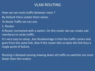
Understanding How InterVLAN Routing Works Network devices in different VLANs cannot communicate with one another without a router to route traffic between the VLANs. In most network environments, VLANs are associated with individual networks or subnetworks.
Configuring VLANs helps control the size of the broadcast domain and keeps local traffic local. However, when an end station in one VLAN needs to communicate with an end station in another VLAN, interVLAN communication is required. This communication is supported by interVLAN routing. You configure one or more routers to route traffic to the appropriate destination VLAN.
However, the real power of virtual networking comes from its ability to affect VLAN topologies that extend beyond single sites to combine multiple LANs across an organization's backbone network. Cisco Systems now offers a comprehensive VLAN solution that can bring together geographically dispersed users across an enterprise network to form VLAN workgroup topologies. Regardless of whether the network comprises Asynchronous Transfer Mode (ATM), Fiber Distributed Data Interface (FDDI), Ethernet/Fast Ethernet, Token Ring, or serial links, the Cisco product line now offers the advantages of virtualization.
The degree of flexibility and control that virtual networking offers is unprecedented. Regardless of physical location or interface type, network managers can define workgroups based on logical function rather than physical location through simple port configuration. Using switches and routers that have embedded VLAN intelligence obviates the need for expensive, time-consuming recabling to extend connectivity in switched LAN environments.
New Cisco IOS VLAN Services Make "Virtual" a Reality Virtual networking has rapidly become one of the major new areas in the internetworking industry. Virtual networking refers to the ability of switches and routers to configure logical topologies on top of the physical network infrastructure, allowing any arbitrary collection of LAN segments within a network to be combined into an autonomous user group, appearing as a single LAN.
Virtual LANs (VLANs) offer significant benefits in terms of efficient use of bandwidth, flexibility, performance, and security. VLAN technology functions by logically segmenting the network into different broadcast domains so that packets are only switched between ports that are designated for the same VLAN. Thus, by containing traffic originating on a particular LAN only to other LANs within the same VLAN, switched virtual networks avoid wasting bandwidth, a drawback inherent in traditional bridged/switched networks where packets are often forwarded to LANs that do not require them. This approach also improves scalability, particularly in LAN environments that support broadcast- or multicast-intensive protocols and applications that flood packets throughout the network. Figure 1 depicts a typical VLAN, where traffic is only switched between LAN interfaces that belong to the same VLAN. Here, the criteria for VLAN membership is departmental function; however, users could also be combined in VLAN topologies based upon a common protocol or subnet address.
Understanding VLANs A VLAN is a switched network that is logically segmented by function, project team, or application, without regard to the physical locations of the users. VLANs have the same attributes as physical LANs, but you can group end stations even if they are not physically located on the same LAN segment. Any switch port can belong to a VLAN, and unicast, broadcast, and multicast packets are forwarded and flooded only to end stations in the VLAN. Each VLAN is considered a logical network, and packets destined for stations that do not belong to the VLAN must be forwarded through a router or bridge.
Because a VLAN is considered a separate logical network, it contains its own bridge Management Information Base (MIB) information and can support its own implementation of spanning tree.
Understanding How InterVLAN Routing Works Network devices in different VLANs cannot communicate with one another without a router to route traffic between the VLANs. In most network environments, VLANs are associated with individual networks or subnetworks.
Subnets and VLANs Cisco recommends that you maintain a one-to-one relationship between subnets and VLANs. This means that all stations residing in or ports configured on the same VLAN are assigned network addresses with the same subnet. If you wish to configure your VLAN differently from the existing subnets, you must reassign the IP addresses on the subnets to match your intended VLAN configuration.
In order to create VLANs, you must decide how to configure the following items: • What VLAN Trunking Protocol (VTP) domain name and VTP mode will be used on this switch? • What ports on the switch will belong to which VLAN? • Will you need to have communication between VLANs, or will they be isolated? If you require communication between VLANs, you will need to use a L3 routing device, such as an external Cisco router or an internal router module such as a Route Switch Module (RSM) or a Multilayer Switch Feature Card (MSFC).
Recording the Plan The table should contain the following information: • VLAN name • Switch type, name, slot, port number and port type of the proposed VLAN • Subnet of each VLAN assignment • Location where you plan to connect a router(s) • User name and user location
Number of VLANs and Users • The maximum number of users that you can define per known network is 1000. • Cisco recommends that a VLAN contain no more than 150 to 200 users.
Maximum Number of Supported VLANs Switch Model Number of Supported VLANs • Catalyst 2950-12 64 • Catalyst 2950-24 64 • Catalyst 2950C-24 250 • Catalyst 2950G-12-EI 250 • Catalyst 2950G-24-EI 250 • Catalyst 2950G-48-EI 250 • Catalyst 2950G-24-EI-DC 250 • Catalyst 2950T-24 250
Configuring VTP and VLANs on the Switch To successfully configure a router for interVLAN routing, you must configure VTP and create and configure VLANs on the switch.
Because a trunk link carries traffic, or frames, from multiple VLANs, the switch must have a method of identifying which VLAN a frame belongs to. Cisco supports four methods of frame identification: • Cisco Inter-Switch Link (ISL)—The Cisco proprietary trunking method used over Fast Ethernet, Gigabit Ethernet, and EtherChannel • IEEE 802.1Q—The IEEE industry standard trunking method, also used over Fast Ethernet, Gigabit Ethernet, and EtherChannel • 802.10—The Cisco proprietary method of trunking over Fiber Distributed Data Interface (FDDI) • LAN Emulation (LANE)—The IEEE standard for trunking over Asynchronous Transfer Mode (ATM) networks
Virtual LAN Standardization - IEEE 802.1Q Cisco Systems pioneered the frame tagging technique for virtual LANs with both the ISL protocol and the use of the IEEE 802.10 Standard and has leveraged that experience to take a leadership role in defining the emerging, functionally equivalent IEEE 802.1Q virtual LAN Standard. It is anticipated that this standard with be ratified later in 1997 following which the Cisco IOS(tm) will offer the same comprehensive capabilities for IEEE 802.1Q based vLANs as are currently available with ISL, IEEE 802.10 and LAN Emulation based virtual LANs. Support for IEEE 802.1Q will be delivered via a regular software upgrade available on Cisco IOS(tm) router and switch platforms.
While configuring 802.1Q trunking it is very important to match the native VLAN across the link. In the Cisco IOS software versions earlier than 12.1(3)T, you cannot define the native VLAN explicitly, as the encapsulation dot1Q 1 native command under the sub-interface is not available. In the earlier Cisco IOS versions, it is important not to configure VLAN1 interface as a sub-interface. The router then expects a tag dot1q frame on VLAN1 and the switch is not expecting a tag on VLAN1. As a result, no traffic will pass between VLAN1 on the switch and the router.
Using the VLAN Trunk Protocol VTP is a Layer 2 messaging protocol that maintains VLAN configuration consistency by managing the addition, deletion, and renaming of VLANs on a network-wide basis. VTP minimizes misconfigurations and configuration inconsistencies that can cause several problems, such as duplicate VLAN names, incorrect VLAN-type specifications, and security violations.
By default, a Catalyst 2950, 2900 XL, or 3500 XL switch is in the no-management-domain state until it receives an advertisement for a domain over a trunk link (a link that carries the traffic of multiple VLANs) or until you configure a domain name. The default VTP mode is server mode, but VLAN information is not propagated over the network until a domain name is specified or learned
VTP server • In this mode, you can create, modify, and delete VLANs and specify other configuration parameters (such as VTP version) for the entire VTP domain. VTP servers advertise their VLAN configurations to other switches in the same VTP domain and synchronize their VLAN configurations with other switches based on advertisements received over trunk links. • In VTP server mode, VLAN configurations are saved in nonvolatile RAM. VTP server is the default mode.
VTP client • In this mode, a VTP client behaves like a VTP server, but you cannot create, change, or delete VLANs on a VTP client. • In VTP client mode, VLAN configurations are saved in nonvolatile RAM.
VTP transparent • In this mode, VTP transparent switches do not participate in VTP. A VTP transparent switch does not advertise its VLAN configuration and does not synchronize its VLAN configuration based on received advertisements. However, transparent switches do forward VTP advertisements that they receive from other switches. You can create, modify, and delete VLANs on a switch in VTP transparent mode. • In VTP transparent mode, VLAN configurations are saved in nonvolatile RAM, but they are not advertised to other switches.
Communication Between VLANs Communication between VLANs is accomplished through routing, and the traditional security and filtering functions of the router can be used. Cisco IOS software provides network services such as security filtering, quality of service (QoS), and accounting on a per VLAN basis. As switched networks evolve to distributed VLANs, Cisco IOS provides key inter-VLAN communications and allows the network to scale.
VLAN Colors VLAN switching is accomplished through frame tagging where traffic originating and contained within a particular virtual topology carries a unique VLAN identifier (VLAN ID) as it traverses a common backbone or trunk link. The VLAN ID enables VLAN switching devices to make intelligent forwarding decisions based on the embedded VLAN ID. Each VLAN is differentiated by a color, or VLAN identifier. The unique VLAN ID determines the frame coloring for the VLAN. Packets originating and contained within a particular VLAN carry the identifier that uniquely defines that VLAN (by the VLAN ID).
The VLAN ID allows VLAN switches and routers to selectively forward packets to ports with the same VLAN ID. The switch that receives the frame from the source station inserts the VLAN ID and the packet is switched onto the shared backbone network. When the frame exits the switched LAN, a switch strips header and forwards the frame to interfaces that match the VLAN color. If you are using a Cisco network management product such as VlanDirector, you can actually color code the VLANs and monitor VLAN graphically.
Why Implement VLANs? Network managers can group logically networks that span all major topologies, including high-speed technologies such as, ATM, FDDI, and Fast Ethernet. By creating virtual LANs, system and network administrators can control traffic patterns and react quickly to relocations and keep up with constant changes in the network due to moving requirements and node relocation just by changing the VLAN member list in the router configuration. They can add, remove, or move devices or make other changes to network configuration using software to make the changes.
Issues regarding benefits of creating VLANs should have been addressed when you developed your network design. Issues to consider include • Scalability • Performance improvements • Security • Network additions, moves, and changes
Switch Configuration • First we will configure the switch with VTP. Switch1#vlan database Switch1(vlan)#vtp server Switch1(vlan)#vtp domain VCC Switch2#vlan database Switch2(vlan)#vtp domain VCC Switch2(vlan)#vtp client
Switch Configuration (cont’d) • Now we will set up the 2 VLAN’s switch1#vlan database switch1(vlan)#vlan 2 name VLAN2 switch1(vlan)#vlan 3 name VLAN3 • Because you set up VTP, switch2 should learn about VLAN2 and VLAN3 automatically. • To show that you have your VLAN’s configured use: switch1#show vlan brief
Switch Configuration (cont’d) • Now we will assign the 2 VLAN’s to ports 2 and 3 switch1(config)#int fa 0/2 switch1(config-if)#switchport access vlan 2 switch1(config)#int fa 0/3 switch1(config-if)#switchport access vlan 3 • You must configure the ports on both switches.
Switch Configuration (cont’d) • Now we must set up the trunk line. We will use port 12. You have to configure this on both switches. Switch1(config)#int fa 0/12 Switch1(config-if)#switchport mode trunk • To check the trunk port to make sure it is functioning properly, use: Switch1#show int fa 0/12 switchport • You should also notice the light on the port is green.
Station Configuration • We will configure four stations in all, two for each VLAN. • The cable ID’s are: VLAN2: 200.202.202.0 VLAN3: 200.203.203.0 • The stations on Switch 1 will be host .11 • The stations on Switch 2 will be host .12
VLAN Testing • To check to see if your VLAN’s are working properly, from the workstations, you should be able to ping stations on your own VLAN, but not stations on other VLAN’s. • To remedy this, we use Inter VLAN Routing.
Router Configuration • We will now configure the router. Router#config t Router(config)#int fa 0/0.1 Router(config-subif)#ip add 200.202.202.1 255.255.255.0 Router(config-subif)#encap dot1q 2 Router(config)#int fa 0/0.2 Router(config-subif)#ip add 200.203.203.1 255.255.255.0 Router(config-subif)#encap dot1q 3 • You must specify the encapsulation type, in this case we are using 802.1q. We have to use this encapsulation type because we are using 2950 switches.
Router Configuration (cont’d) • Don’t forget to setup your routing protocol!! Router#config t Router(config)#router rip Router(config-router)#network 200.202.202.0 Router(config-router)#network 200.203.203.0