Download
1 / 51
520 likes | 787 Views
27. Electromagnetic Induction. Induced Currents Faraday’s Law Induction & Energy Inductance Magnetic Energy Induced Electric Fields. It takes fourteen 110-car trainloads of each week to fuel this power plant.

E N D
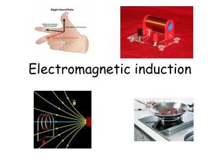
27. Electromagnetic Induction Induced Currents Faraday’s Law Induction & Energy Inductance Magnetic Energy Induced Electric Fields
It takes fourteen 110-car trainloads of each week to fuel this power plant. What feature of the equation ε = -dΦB/dt demands this prodigious fuel consumption? The minus sign, which denotes energy conservation in electromagnetic induction.
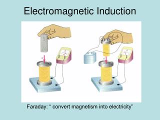
27.1. Induced Currents 4 results from Faraday / Henry (1831) v = 0, I = 0 v > 0, I > 0 1. Current induced in coil by moving magnet bar. v >> 0, I >> 0 v < 0, I < 0 2. Moving the coil instead of the magnet gives the same result.
3. An induced current also results when a current-carrying circuit replaces the magnet. 4. A current is also induced when the current in an adjacent circuit changes. changing B induces currents (electromagnetic induction)
27.2. Faraday’s Law • Magnetic flux • Flux & Induced EMF
Magnetic flux Magnetic flux: Reminder: For a uniform B on a flat surface: Move magnet right more lines thru loop
Example 27.1. Solenoid A solenoid of circular cross section has radius R, consists of n turns per unit length, and carries current I. Find the magnetic flux through each turn of the solenoid. I B B out of plane
Example 27.2. Nonuniform Field A long, straight wire carries current I. A rectangular wire loop of dimensions l by w lies in a plane containing the wire, with its closest edge a distance a from the wire, and its dimension l parallel to the wire. Find the magnetic flux through the loop. Area element for integration
Flux & Induced EMF Faraday’s law of induction: The induced emf in a circuit is proportional to the rate of change of magnetic flux through any surface bounded by that circuit. C is CCW about S. Note: dB/dt can be due to • changing B caused by • relative motion between circuit & magnet, • changing current in adjacent circuit, • changing area of circuit, • changing orientation between B & circuit. C C
Example 27.3. Changing B A wire loop of radius 10 cm has resistance 2.0 . The plane of the loop is perpendicular to a uniform B that’s increasing at 0.10 T/s. Find the magnitude of the induced current in the loop. S C I CCW
Example 27.3. Changing B A wire loop of radius 10 cm has resistance 2.0 . The plane of the loop is perpendicular to a uniform B that’s increasing at 0.10 T/s. Find the magnitude of the induced current in the loop. S C I CCW
Example 27.4. Changing Area Two parallel conducting rails a distance l apart are connected at one end by a resistance R. A conducting bar completes the circuit, joining the two rails electrically but free to slide along. The whole circuit is perpendicular to a uniform B, as show in figure. Find the current when the bar is pulled to the right with constant speed v. Let x = 0 be at the left end of rail. S C I CCW x
Example 27.4. Changing Area Two parallel conducting rails a distance l apart are connected at one end by a resistance R. A conducting bar completes the circuit, joining the two rails electrically but free to slide along. The whole circuit is perpendicular to a uniform B, as show in figure. Find the current when the bar is pulled to the right with constant speed v. Let x = 0 be at the left end of rail. S C I CCW x
27.3. Induction & Energy m I Direction of emf is to oppose magnet’s motion. RH rule: thumb // m. Loop ~ magnet with N to left. Magnet moving right Lenz’s law : Direction of induced emf is such that B created by the induced current opposes the changes in that created the current. m I RH rule: thumb // m. Loop ~ magnet with S to left. Magnet moving left
GOT IT? 27.1 You push a bar magnet towards a loop, with the north pole toward the loop. If you keep pushing the magnet straight through the loop, what will be the direction of the current as you pull it out the other side? Will you need to do work, or will work be done on you? Reversed 逆轉 I I m m
Motional EMF & Len’s Law Motional emf: induced emf due to motion of conductor in B. Square loop of sides L & resistance R pulled with constant speed v out of uniform B. Force on e: downward force • upward I (CW) Force on current carrying wire:
> 0 S I C CW x Work done is used to heat up circuit ( E conservation ).
< 0 S I C CW x Work done is used to heat up circuit ( E conservation ).
GOT IT? 27.2 What will be the direction of the current when the loop first enters the field from the left side? S Current is CCW C
GOT IT? 27.2 What will be the direction of the current when the loop first enters the field from the left side? S Current is CCW C
Application. Electric Generators World electricity generation ~ 2TW. Rotating loop changes & induces emf. Rotating slip rings. Sinusoidal AC output Work required due to Lenz’s law. Electric load Stationary brushes Rotating conducting loop Hand-cranked generator ~ 100W
GOT IT? 27.3 If you lower the electrical resistance connected across a generator while turning the generator at a constant speed, will the generator get easier or harder to turn? constant speed fixed peak emf lower R higher power
Example 27.5. Designing a Generator An electric generator consists of a 100-turn circular coil 50 cm in diameter. It’s rotated at f = 60 rev/s to produce standard 60 Hz alternating current. Find B needed for a peak output voltage of 170 V, which is the actual peak in standard 120 V household wiring. Loop rotation
EM induction is basis of magnetic recording ( audio, video, computer disks, …). Iron Coil Card motion Modern hard disks: Giant magnetoresistance. Magnetic strip Information stored in magnetization pattern Swiping a credit card. Patterns of magnetization on the strip induce currents in the coil.
Eddy Currents Eddy current: current in solid conductor induced by changing . Usage: non-frictional brakes for rotating saw blades, train wheels, … Application: Metal Detectors Induced Current Nothing between coils Current detector AC Strong I Transmitter coil Receiver coil Weak I : alarm. Metal between coils
GOT IT? 27.4 • A copper penny falls on a path that takes it between the poles of a magnet. • Does it hit the ground going • faster, • slower, • at the same speed as if the magnet weren’t present? Eddy current dissipates KE.
Closed & Open Circuits B of induced I points out of page Setting n // Bin C is CCW & < 0 Bin d /d t < 0 E > 0 I is CCW RH rule gives CCW I Bin C +_ B E > 0
GOT IT? 27.5 • A long wire carries a current I as shown. • What’s the direction of the current in the circular conducting loop when I is • increasing and • decreasing? CCW CW Setting n // B C is CW & > 0 I B d /d t > 0 E < 0 Iind is CCW B
GOT IT? 27.5 • A long wire carries a current I as shown. • What’s the direction of the current in the circular conducting loop when I is • increasing and • decreasing? CCW CW Setting n // B C is CCW & < 0 I B d /d t < 0 E > 0 Iind is CCW B
27.4. Inductance Inductance: Mutual Inductance: Changing current in one circuit induces an emf in the other. Large inductance: two coils are wound on same iron core. Applications: Transformers, ignition coil, battery chargers, … Self-Inductance: Changing current induces emf in own circuit & opposes further changes. Applications: Inductors frequency generator / detector … [ L ] = T m2 / A = Henry
Example 27.6. Solenoid A long solenoid of cross section area A and length l has n turns per unit length. Find its self-inductance. B of solenoid:
+E direction = V along I. back emf Rapid switching of inductive devices can destroy delicate electronic devices. dI /d t < 0
Inductor (lower voltage) (lower voltage) E E + (higher voltage) + (higher voltage)
GOT IT? 27.6 • Current flows left to right through the inductor shown. • A voltmeter connected across the inductor gives a constant reading, and shows that the left end of the inductor is positive. • Is the current in the inductor • increasing, • decreasing, or • steady? Why? V along I E < 0 dI/dt > 0
Example 27.7. Dangerous Inductor A 5.0-A current is flowing in a 2.0-H inductor. The current is then reduced steadily to zero over 1.0 ms. Find the magnitude & direction of the inductor emf during this time. + here ( E > 0 ) helps keep I flowing
Inductors in Circuits Current through inductor can’t change instantaneously. Switch just closed : I = 0, dI/dt 0; | EL | = E0 L ~ open circuit. Long after switch closing: I 0, dI/dt = 0; EL= 0; L ~ wire. Switch open: I = 0
+_ I V = IR But rate is EL< 0 ; | EL | Inductive time constant = L / R c.f. capacitive time constant = RC
Example 27.8. Firing Up a Electromagnet A large electromagnet used for lifting scrap iron has self-inductance L = 56 H. It’s connected to a constant 440-V power source; the total resistance of the circuit is 2.8 . Find the time it takes for the current to reach 75% of its final value.
Switch at B, battery’s shorted out. I exponentially. Switch at A, I. Short times: IL can’t change instantaneously. Long times: EL = 0 ; inductor wire.
Conceptual Example27.1. Short & long Times The switch in figure is initially open. It is then closed and, a long time later, reopened. What’s the direction of the current in R2 after the switch is reopened. right after switch closed: L ~ open circuit. Long after switch closed : L ~ short circuit. right after switch reopened I in L ~ continues.
Making the Connection Verify that the current in just after the switch is reopened has the value indicated Immediately after the switch is closed: L ~ open circuit. Long time after the switch is closed: Immediately after 2nd switch opening : L ~ short circuit. I in L ~ continues.
27.5. Magnetic Energy Any B contains energy. This eruption of a huge prominence from the sun’s surface releases energy stored in magnetic fields.
Magnetic Energy in an Inductor RL circuit: Power from battery Power dissipated Power taken by inductor Energy stored in inductor:
Example 27.10. MRI Disaster • Superconducting electromagnets like solenoids in MRI scanners store a lot of magnetic energy. • Loss of coolant is dangerous since current quickly decays due to resistance. • A particular MRI solenoid carries 2.4 kA and has a 0.53 H inductance. • When it loses superconductivity, its resistance goes abruptly to 31 m. Find • the stored magnetic energy, and • the rate of energy release at the instance the superconductivity is lost. In practice, Cu / Ag are incorporated into the superconducting wires to reduce R.
Magnetic Energy Density Solenoid with length l & cross-section area A : (Eg. 27.6) Magnetic Energy Density : c.f. electric energy density :
27.6. Induced Electric Fields EMF acts to separate charges: Battery: chemical reaction Motional emf: F = v B. Stationary loop in changing B : induced E Faraday’s law Induced E forms loop. Static E begins / ends on charge.
Example 27.11. Solenoid A long solenoid has circular cross section of radius R. The solenoid current is increasing, & as a result so is B in solenoid. The field strength is given by B = b t, where b is a constant. Find the induced E outside the solenoid, a distance r from the axis. Symmetry E lines are circles. Loop for Faraday’s law S CCW S in C cw
Example 27.11. Solenoid A long solenoid has circular cross section of radius R. The solenoid current is increasing, & as a result so is B in solenoid. The field strength is given by B = b t, where b is a constant. Find the induced E outside the solenoid, a distance r from the axis. Symmetry E lines are circles. Loop for Faraday’s law S CCW S out C ccw
Conservative & Nonconservative Electric Fields E For stationary charges (electrostatics) : W against E E is conservative Induced fields (electromagnetics) : E does W E is non-conservative
GOT IT? 27.7 The figure shows three resistors in series surrounding an infinitely long solenoid with a changing magnetic field; the resulting induced electric field drives a current counterclockwise, as shown. Two identical voltmeters are shown connected to the same points A and B. What does each read? Explain any apparent contradiction. Hint: this is a challenging question! VA VB = IR VA VB = 2IR