Download
1 / 54
730 likes | 1.33k Views
Electromagnetic Induction. Faraday: “ convert magnetism into electricity”. What we know…. Current in a wire generates magnetic field Field of a solenoid is similar to that of a bar magnet Strength of magnetic field depends on permeability ( magnetic properties of magnet)

E N D
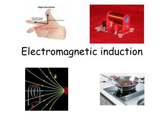
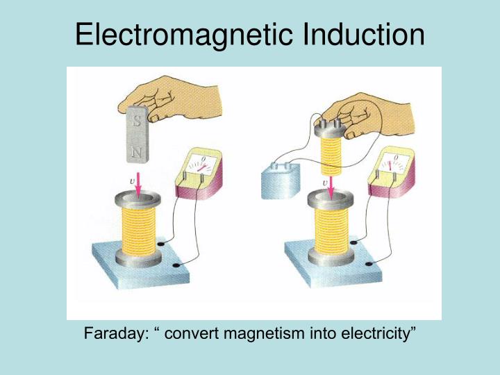
Electromagnetic Induction Faraday: “ convert magnetism into electricity”
What we know… • Current in a wire generates magnetic field • Field of a solenoid is similar to that of a bar magnet • Strength of magnetic field depends on permeability ( magnetic properties of magnet) • Interaction between magnetic field and electric field results in a magnetic force ( as in electric motor) Can a magnetic field induce a current in a wire?
Electromagnetic induction Electromagnetic induction is the process of generating current by: - moving a wire through a magnetic field, or -moving a magnetic field across a wire ( conductor) [ relative motion between the magnetic field and a wire]
Michael Faraday’s Experiment Closed loop of wire ( attached to galvanometer) is placed in a magnetic field • No current generated in wire if: • Wire is stationary ( not moving) • Wire movesparallel to magnetic field • Current is generated in wire if: • Wire moves relative to the magnetic field • Wire moves perpendicular to magnetic field • ( maximum current generated)
Direction of the current When the direction of magnetic field changes, the direction of the current changes How can you tell the direction of the current?
4th Right Hand Rule Palm- direction of current (Force on the charge) Thumb – direction the wire moves ( velocity) Fingers- magnetic field (B) To determine the force on a charge or direction of conventional current
Use the 4th Right Hand Rule to find the direction of the induced current in this wire
If the wire moves to the right, in which direction does the induced current move? In what direction should the wire be moved, relative to the magnetic field to generate the minimum voltage? 0 voltage - Parallel to magnetic field
Electromotive Force (EMF) Measured in Volts (V) Makes current flow from lower to higher potential EMF is the Potential Difference across a wire moving in a magnetic field ( or voltage given to a charge by a battery) Wire moves through a magnetic field Force is exerted on a charge in the wire Charge moves in the direction of the force = work is done Electrical Potential energy increases Difference in potential is called induced EMF
EMF depends on: -velocity of the wire, [v] - the length of the wire [L] - the magnetic field, [B] EMF = BLv( sin θ) [ sin θ – if wire in not perpendicular to magnetic field- find the perpendicular component of the velocity] The Current induced in the wire depends on: - v, L B and resistance in the wire V= Voltage v= velocity
Units of EMF • EMF = BLv = = units = Volts Q= It C= As = W=Fxd J=Nm Potential energy is work done per unit charge = J/C = Volts
Solve 1 • A 20m long wire moves at 4m/s at an angle of 450 through a magnetic field. An EMF of 40V is induced in the wire. What is the strength of the magnetic field? EMF = BLv sinθ 40V = B x 20 x 4 x sin 45 B = 0.707 T
Solve 2 calculations L v B 900 A straight wire, 0.30 m long, moves at a constant speed of 10.0 m/sperpendicular to a 0.20-T magnetic field. • What is the induced EMF in the wire? b. What is the current in the wire if it is part of a circuit with a resistance of 25Ω ? EMF = Blvsinθ = 0.2 x 0.3 x 10 sin 90 = 0.6V R V = I x R 0.6 = I x 25
What is the induced emf in a wire 0.5m long moving at right angles to a 0.04T magnetic field with a velocity of 5m/s? 0.1
Challenge A square wire loop moves perpendicularly through a magnetic field of strength 1.75 T at a velocity of 2.5 m/s, The direction of the magnetic field is out of the page. 1. If the wire loop is 10 cm on a side, calculate the magnitude of the induced electromotive force in the wire segment: a. AB. b. BC. c. CD. d. With a total resistance of 130 Ω, calculate the induced current in the wire loop. EMF = Blvsin 90 Use 4th right hand rule – EMF = 0V No magnetic field – EMF = 0V
A: 0 degrees B: 90 degrees D B D B C A C A B D B D A C A C C: 180 degrees D: 270 degrees In which of these will maximum EMF be induced? A and C
Application of induced EMF e.g. Microphone
Application of induced EMF a diaphragm in a microphone is attached to a coil of wire that is free to move in a magnetic field. 1. Sound waves vibrate the diaphragm 2. This moves the coil in the magnetic field. 3. The motion of the coil induces an EMF across the ends of the coil. • Voltage can be increased by electronic devices How is an EMF produced in a microphone
Sound wave converted to electrical signal The induced EMF varies as the frequency of the sound varies. This converts sound energy to electrical signal
Magnetic flux • Magnetic flux is the number of magnetic field lines passing through a surface placed in a magnetic field.
Magnetic flux and Faraday’s law of Induction An external magnetic field passes through a region at an angle θ to the region Perpendicular component of magnetic field = Bcosθ Magnetic field θ area Magnetic flux Φ is the product of the perpendicular component of the magnetic field and cross sectional area A
Magnetic flux and Faraday’s law of Induction Φ = BA cos θ Φ = magnetic flux Weber (Wb) B = magnetic field strength Tesla (T) A = cross sectional area (m2) 1 Wb = 1 T.m2 Magnetic flux Φ is the product of the perpendicular component of the magnetic field and cross sectional area A
Perpendicular to surface Magnetic field lines perpendicular to Surface Flux is maximum Perpendicular to surface Magnetic field lines parallel to surface Flux is 0 Φ = BA cos 90 = 0 Φ = BA cos 0 = BA
The circular loop in the figure has a radius of 4 cm and makes an angle of 230 with a 2-T magnetic field. What is the flux through the loop? Φ = BA cos θ A = πr2 = π (4/100)2 = 5 x 10⁻³ m2 = 2 x (5 x 10-3) cos 23 = 9 x 10⁻³Wb
A square with sides of length 2 m is perpendicular to a magnetic field of strength 10 T. If the square is rotated by 60º, what is the change in magnetic flux through the square? • =BA cos θ - = BA cosθ • = 10 x 2x 2 x cos 0 - 10 x 2 x 2 x cos 600 • = 40 - 20 • = 20 Wb
Magnetic field strength Magnetic flux density = magnetic flux per cross sectional area = Wb/m2 Φ = BA Φ/A = B ( magnetic field strength) = magnetic flux density
Faraday’s law of Induction : Induced motional EMF is due to the rate of change of the magnetic flux If a coil has a number of turns use the equation:
problem A coil is made of 10 turns of wire and has a diameter of 5cm. The coil is passing through the field in such a way that the axis of the coil is parallel to the field. The strength of the field is 0.5T. a. What is the change in the magnetic flux? B. If an average EMF of 2V is observed, for how long was the flux changing? -9.8 x 10⁻⁴ 4.9 x 10⁻³s
recap: 1. What is the induced EMF in a wire that is 20 cm long, moving at an angle of 300 to a 0.08 T magnetic field with a velocity of 5 m/s 2. A flat 300 turn coil has a resistance of 3Ώ. The coil covers an area of 15cm2. At what rate must the magnetic field change in order to induce a current of 0.75 A in the coil? ( find the rate of change of magnetic field) EMF = I x R Φ = BA cosθ EMF = BLv( sin θ)
Electrical generators Pg 675 PPP
Electrical generators • Invented by MICHAEL FARADAY • Electrical generators change mechanical energy to electrical energy Made up of: Wire loop placed in How an electric generator works The armature rotates in the magnetic field When the wire is perpendicular to magnetic field, it cuts the magnetic field- EMF induced Magnetic field
To determine the direction of the induced current – use 4th right hand rule To increase the strength of the magnetic field: 1. Wire is wound around an iron core – called an armature To increase the induced EMF: - Increase the length of the coil by increasing the number of turns How does the strength and direction of the current change?
Wire is perpendicular to magnetic field Wire is parallel to magnetic field When coil is horizontal ( 900 to magnetic field) Maximum EMF induced When coil is vertical (00 to magnetic field) Minimum (0) EMF induced When is maximum current produced?
Is current induced in all sides of the loop? Using the 4th right hand rule We see that the current will move to the side of the wire- no EMF induced. EMF is not induced in this side of the coil (AB or CD) A B D C if the coil moves clockwise ( as shown), current moves anticlockwise ( use right hand rule) Magnetic field reverses direction every ½ turn- produce alternating current EMF induced = BLv(sinθ) L= AD or BC
Voltage-time graph for ac current Equation for this graph: V= Vmax cos 2πft f = frequency of alternation
How can we increase the frequency of a generator? Increase the number of magnetic pole pairs
Motors and Generators Converts electrical energy to mechanical energy Voltage is placed across an armature in a magnetic field Voltage cause current to flow in the coil- armature turns Converts mechanical energy to electrical energy Mechanical energy turns armature in a magnetic field. Induced voltage cause current to flow
Electric generator As the armature turns, the wire loops cut through the magnetic field lines and induce an EMF. Made up of a number of wire loops placed in a strong magnetic field to increase the strength of the magnetic field, wire is wound around an iron core (armature) which rotates freely EMF depends on the length of wire. Increasing the number of loops in the armature increases the wire length, magnetic field induces an EMF. the induced EMF produces an electric current
Electric generators http://www.animations.physics.unsw.edu.au/jw/electricmotors.html#DCmotors
Explain the construction and working of an AC generator • PrincipleWhen a straight conductor is moved in a magnetic field, then a current is induced in the conductor. • It is based on electromagnetic induction.
Explain the construction and working of an AC generator Made up of Permanent magnets armature made up of a number of turns of wire on a soft iron core brush & slip-rings: allows the armature to turn freely and allows the current to pass into the external circuit • An energy source turns the armature at a fixed frequency. E.g. 60Hz in US, 50Hz - UAE
Alternating current AC generators The Current changes direction in the external circuit • As the armature turns, the alternating current varies between a maximum value and zero • How is the AC generator different from a motor?
As the armature turns the velocity vector perpendicular to the magnetic field changes.The flux changes continuously with timeThis change in magnetic flux induces an emf The direction of the induced emf is reversed after every half rotation of the coil.Thus in one rotation of the coil, the current changes its direction twice in the coil
Average power The power produced by a generator is the product of the current and the voltage. P = I x V • power varies because both current and voltage vary. • Power is always positive because I and V are either both positive or both negative.
DC generators Split ring commutators : Act as full-wave rectifiers change the alternating current in the coil to DC in the external circuit
Average power PAC, is half the maximum power
Effective current If we express AC POWER in terms of effective current, then P = I2R PAC = I2eff R But PAC = ½ PACmax I2eff R = ½ I2max R Ieff = 0.707 Imax