Download

1 / 58
600 likes | 1.14k Views
ARM. Advanced RISC Machines. The ARM Instruction Set. Main features of the ARM Instruction Set. All instructions are 32 bits long. Most instructions execute in a single cycle. Every instruction can be conditionally executed. A load/store architecture

E N D
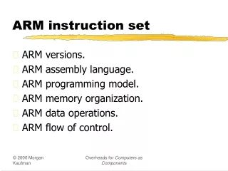
ARM Advanced RISC Machines The ARM Instruction Set
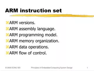
Main features of theARM Instruction Set • All instructions are 32 bits long. • Most instructions execute in a single cycle. • Every instruction can be conditionally executed. • A load/store architecture • Data processing instructions act only on registers • Three operand format • Combined ALU and shifter for high speed bit manipulation • Specific memory access instructions with powerful auto-indexing addressing modes. • 32 bit and 8 bit data types • and also 16 bit data types on ARM Architecture v4. • Flexible multiple register load and store instructions • Instruction set extension via coprocessors
Processor Modes • The ARM has six operating modes: • User (unprivileged mode under which most tasks run) • FIQ (entered when a high priority (fast) interrupt is raised) • IRQ (entered when a low priority (normal) interrupt is raised) • Supervisor (entered on reset and when a Software Interrupt instruction is executed) • Abort (used to handle memory access violations) • Undef (used to handle undefined instructions) • ARM Architecture Version 4 adds a seventh mode: • System (privileged mode using the same registers as user mode)
The Registers • ARM has 37 registers in total, all of which are 32-bits long. • 1 dedicated program counter • 1 dedicated current program status register • 5 dedicated saved program status registers • 30 general purpose registers • However these are arranged into several banks, with the accessible bank being governed by the processor mode. Each mode can access • a particular set of r0-r12 registers • a particular r13 (the stack pointer) and r14 (link register) • r15 (the program counter) • cpsr (the current program status register) and privileged modes can also access • a particular spsr (saved program status register)
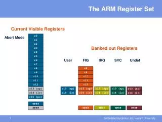
General registers and Program Counter User32 / System FIQ32 Supervisor32 Abort32 IRQ32 Undefined32 r0 r0 r0 r0 r0 r0 r1 r1 r1 r1 r1 r1 r2 r2 r2 r2 r2 r2 r3 r3 r3 r3 r3 r3 r4 r4 r4 r4 r4 r4 r5 r5 r5 r5 r5 r5 r6 r6 r6 r6 r6 r6 r7 r7 r7 r7 r7 r7 r8 r8_fiq r8 r8 r8 r8 r9 r9_fiq r9 r9 r9 r9 r10 r10_fiq r10 r10 r10 r10 r11 r11_fiq r11 r11 r11 r11 r12 r12_fiq r12 r12 r12 r12 r13 (sp) r13_fiq r13_svc r13_abt r13_irq r13_undef r14 (lr) r14_fiq r14_svc r14_abt r14_irq r14_undef r15 (pc) r15 (pc) r15 (pc) r15 (pc) r15 (pc) r15 (pc) Program Status Registers cpsr cpsr cpsr cpsr cpsr cpsr sprsr_fiq sprsr_fiq sprsr_fiq sprsr_fiq sprsr_fiq spsr_fiq spsr_svc spsr_abt sprsr_fiq sprsr_fiq sprsr_fiq sprsr_fiq sprsr_fiq spsr_irq spsr_undef sprsr_fiq sprsr_fiq sprsr_fiq sprsr_fiq sprsr_fiq Register Organisation
Registers in use Registers in use User Mode FIQ Mode r0 r0 r1 r1 r2 r2 r3 r3 r4 r4 r5 r5 r6 r6 r7 r7 EXCEPTION r8_fiq r8 r8_fiq r8 r9_fiq r9 r9_fiq r9 r10_fiq r10 r10_fiq r10 r11_fiq r11 r11_fiq r11 r12_fiq r12 r12_fiq r12 r13_fiq r13 (sp) r13_fiq r13 (sp) r14_fiq r14 (lr) r14_fiq r14 (lr) r15 (pc) r15 (pc) Return address calculated from User mode PC value and stored in FIQ mode LR cpsr cpsr spsr_fiq spsr_fiq User mode CPSR copied to FIQ mode SPSR Register Example:User to FIQ Mode
Accessing Registers using ARM Instructions • No breakdown of currently accessible registers. • All instructions can access r0-r14 directly. • Most instructions also allow use of the PC. • Specific instructions to allow access to CPSR and SPSR. • Note : When in a privileged mode, it is also possible to load / store the (banked out) user mode registers to or from memory. • See later for details.
28 4 0 31 8 Z C V N I F T Mode The Program Status Registers (CPSR and SPSRs) Copies of the ALU status flags (latched if the instruction has the "S" bit set). * Condition Code Flags * Interrupt Disable bits. I = 1, disables the IRQ. F = 1, disables the FIQ. * T Bit (Architecture v4T only) T = 0, Processor in ARM state T = 1, Processor in Thumb state N = Negative result from ALU flag. Z = Zero result from ALU flag. C = ALU operation Carried out V = ALU operation oVerflowed * Mode Bits M[4:0] define the processor mode.
Condition Flags Logical Instruction Arithmetic Instruction Flag Negative No meaning Bit 31 of the result has been set (N=‘1’) Indicates a negative number in signed operations Zero Result is all zeroes Result of operation was zero (Z=‘1’) Carry After Shift operation Result was greater than 32 bits (C=‘1’) ‘1’ was left in carry flag oVerflow No meaning Result was greater than 31 bits (V=‘1’) Indicates a possible corruption of the sign bit in signed numbers
The Program Counter (R15) • When the processor is executing in ARM state: • All instructions are 32 bits in length • All instructions must be word aligned • Therefore the PC value is stored in bits [31:2] with bits [1:0] equal to zero (as instruction cannot be halfword or byte aligned). • R14 is used as the subroutine link register (LR) and stores the return address when Branch with Link operations are performed, calculated from the PC. • Thus to return from a linked branch • MOV r15,r14 or • MOV pc,lr
Exception Handlingand the Vector Table • When an exception occurs, the core: • Copies CPSR into SPSR_<mode> • Sets appropriate CPSR bits • If core implements ARM Architecture 4T and is currently in Thumb state, then • ARM state is entered. • Mode field bits • Interrupt disable flags if appropriate. • Maps in appropriate banked registers • Stores the “return address” in LR_<mode> • Sets PC to vector address • To return, exception handler needs to: • Restore CPSR from SPSR_<mode> • Restore PC from LR_<mode>
Instruction fetched from memory Decoding of registers used in instruction Register(s) read from Register Bank Shift and ALU operation Write register(s) back to Register Bank The Instruction Pipeline • The ARM uses a pipeline in order to increase the speed of the flow of instructions to the processor. • Allows several operations to be undertaken simultaneously, rather than serially. • Rather than pointing to the instruction being executed, the PC points to the instruction being fetched. ARM FETCH PC PC - 4 DECODE EXECUTE PC - 8
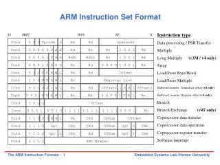
Cond 0 0 0 1 0 B 0 0 Rn Rd 0 0 0 0 1 0 0 1 Rm Cond 0 1 I P U B W L Rn Rd Offset Cond 1 0 0 P U S W L Rn Register List Cond 0 0 0 P U 1 W L Rn Rd Offset1 1 S H 1 Offset2 Cond 0 0 0 P U 0 W L Rn Rd 0 0 0 0 1 S H 1 Rm Cond 1 0 1 L Offset Cond 0 0 0 1 0 0 1 0 1 1 1 1 1 1 1 1 1 1 1 1 0 0 0 1 Rn Cond 1 1 0 P U N W L Rn CRd CPNum Offset Cond 1 1 1 0 Op1 CRn CRd CPNum Op2 0 CRm Cond 1 1 1 0 Op1 L CRn Rd CPNum Op2 1 CRm Cond 1 1 1 1 SWI Number ARM Instruction Set Format 31 28 27 16 15 8 7 0 Cond 0 0 I Opcode S Rn Rd Operand2 Instruction type Data processing / PSR Transfer Multiply Long Multiply (v3M / v4 only) Swap Load/Store Byte/Word Load/Store Multiple Halfword transfer : Immediate offset (v4 only) Halfword transfer: Register offset (v4 only) Branch Branch Exchange (v4T only) Coprocessor data transfer Coprocessor data operation Coprocessor register transfer Software interrupt Cond 0 0 0 0 0 0 A S Rd Rn Rs 1 0 0 1 Rm Cond 0 0 0 0 1 U A S RdHi RdLo Rs 1 0 0 1 Rm
Conditional Execution • Most instruction sets only allow branches to be executed conditionally. • However by reusing the condition evaluation hardware, ARM effectively increases number of instructions. • All instructions contain a condition field which determines whether the CPU will execute them. • Non-executed instructions soak up 1 cycle. • Still have to complete cycle so as to allow fetching and decoding of following instructions. • This removes the need for many branches, which stall the pipeline (3 cycles to refill). • Allows very dense in-line code, without branches. • The Time penalty of not executing several conditional instructions is frequently less than overhead of the branch or subroutine call that would otherwise be needed.
The Condition Field 1001 = LS - C clear or Z (set unsigned lower or same) 1010 = GE - N set and V set, or N clear and V clear (>or =) 1011 = LT - N set and V clear, or N clear and V set (>) 1100 = GT - Z clear, and either N set and V set, or N clear and V set (>) 1101 = LE - Z set, or N set and V clear,or N clear and V set (<, or =) 1110 = AL - always 1111 = NV - reserved. 28 24 20 16 4 0 31 12 8 Cond 0000 = EQ - Z set (equal) 0001 = NE - Z clear (not equal) 0010 = HS / CS - C set (unsigned higher or same) 0011 = LO / CC - C clear (unsigned lower) 0100 = MI -N set (negative) 0101 = PL - N clear (positive or zero) 0110 = VS - V set (overflow) 0111 = VC - V clear (no overflow) 1000 = HI - C set and Z clear (unsigned higher)
Using and updating the Condition Field • To execute an instruction conditionally, simply postfix it with the appropriate condition: • For example an add instruction takes the form: • ADD r0,r1,r2 ; r0 = r1 + r2 (ADDAL) • To execute this only if the zero flag is set: • ADDEQ r0,r1,r2 ; If zero flag set then… ; ... r0 = r1 + r2 • By default, data processing operations do not affect the condition flags (apart from the comparisons where this is the only effect). To cause the condition flags to be updated, the S bit of the instruction needs to be set by postfixing the instruction (and any condition code) with an “S”. • For example to add two numbers and set the condition flags: • ADDS r0,r1,r2; r0 = r1 + r2 ; ... and set flags
31 28 27 25 24 23 0 Cond 1 0 1 L Offset Link bit 0 = Branch 1 = Branch with link Condition field Branch instructions (1) • Branch : B{<cond>} label • Branch with Link : BL{<cond>} sub_routine_label • The offset for branch instructions is calculated by the assembler: • By taking the difference between the branch instruction and the target address minus 8 (to allow for the pipeline). • This gives a 26 bit offset which is right shifted 2 bits (as the bottom two bits are always zero as instructions are word – aligned) and stored into the instruction encoding. • This gives a range of ± 32 Mbytes.
Branch instructions (2) • When executing the instruction, the processor: • shifts the offset left two bits, sign extends it to 32 bits, and adds it to PC. • Execution then continues from the new PC, once the pipeline has been refilled. • The "Branch with link" instruction implements a subroutine call by writing PC-4 into the LR of the current bank. • i.e. the address of the next instruction following the branch with link (allowing for the pipeline). • To return from subroutine, simply need to restore the PC from the LR: • MOV pc, lr • Again, pipeline has to refill before execution continues. • The "Branch" instruction does not affect LR. • Note: Architecture 4T offers a further ARM branch instruction, BX • See Thumb Instruction Set Module for details.
Data processing Instructions • Largest family of ARM instructions, all sharing the same instruction format. • Contains: • Arithmetic operations • Comparisons (no results - just set condition codes) • Logical operations • Data movement between registers • Remember, this is a load / store architecture • These instruction only work on registers, NOT memory. • They each perform a specific operation on one or two operands. • First operand always a register - Rn • Second operand sent to the ALU via barrel shifter. • We will examine the barrel shifter shortly.
Arithmetic Operations • Operations are: • ADD operand1 + operand2 • ADC operand1 + operand2 + carry • SUB operand1 - operand2 • SBC operand1 - operand2 + carry -1 • RSB operand2 - operand1 • RSC operand2 - operand1 + carry - 1 • Syntax: • <Operation>{<cond>}{S} Rd, Rn, Operand2 • Examples • ADD r0, r1, r2 • SUBGT r3, r3, #1 • RSBLES r4, r5, #5
Comparisons • The only effect of the comparisons is to • UPDATE THE CONDITION FLAGS. Thus no need to set S bit. • Operations are: • CMP operand1 - operand2, but result not written • CMN operand1 + operand2, but result not written • TST operand1 AND operand2, but result not written • TEQ operand1 EOR operand2, but result not written • Syntax: • <Operation>{<cond>} Rn, Operand2 • Examples: • CMP r0, r1 • TSTEQ r2, #5
Logical Operations • Operations are: • AND operand1 AND operand2 • EOR operand1 EOR operand2 • ORR operand1 OR operand2 • BIC operand1 AND NOT operand2 [ie bit clear] • Syntax: • <Operation>{<cond>}{S} Rd, Rn, Operand2 • Examples: • AND r0, r1, r2 • BICEQ r2, r3, #7 • EORS r1,r3,r0
Data Movement • Operations are: • MOV operand2 • MVN NOT operand2 Note that these make no use of operand1. • Syntax: • <Operation>{<cond>}{S} Rd, Operand2 • Examples: • MOV r0, r1 • MOVS r2, #10 • MVNEQ r1,#0
The Barrel Shifter • The ARM doesn’t have actual shift instructions. • Instead it has a barrel shifter which provides a mechanism to carry out shifts as part of other instructions. • So what operations does the barrel shifter support?
Barrel Shifter - Left Shift • Shifts left by the specified amount (multiplies by powers of two) e.g. LSL #5 = multiply by 32 Logical Shift Left (LSL) Destination CF 0
Barrel Shifter - Right Shifts Logical Shift Right • Shifts right by the specified amount (divides by powers of two) e.g. LSR #5 = divide by 32 Arithmetic Shift Right • Shifts right (divides by powers of two) and preserves the sign bit, for 2's complement operations. e.g. ASR #5 = divide by 32 Logical Shift Right Destination CF ...0 Arithmetic Shift Right Destination CF Sign bit shifted in
Rotate Right through Carry Destination CF Barrel Shifter - Rotations Rotate Right Rotate Right (ROR) • Similar to an ASR but the bits wrap around as they leave the LSB and appear as the MSB. e.g. ROR #5 • Note the last bit rotated is also used as the Carry Out. Rotate Right Extended (RRX) • This operation uses the CPSR C flag as a 33rd bit. • Rotates right by 1 bit. Encoded as ROR #0. Destination CF
Operand 1 Operand 2 Barrel Shifter ALU Result Using the Barrel Shifter:The Second Operand • Register, optionally with shift operation applied. • Shift value can be either be: • 5 bit unsigned integer • Specified in bottom byte of another register. • Immediate value • 8 bit number • Can be rotated right through an even number of positions. • Assembler will calculate rotate for you from constant.
Second Operand :Shifted Register • The amount by which the register is to be shifted is contained in either: • the immediate 5-bit field in the instruction • NO OVERHEAD • Shift is done for free - executes in single cycle. • the bottom byte of a register (not PC) • Then takes extra cycle to execute • ARM doesn’t have enough read ports to read 3 registers at once. • Then same as on other processors where shift isseparate instruction. • If no shift is specified then a default shift is applied: LSL #0 • i.e. barrel shifter has no effect on value in register.
Second Operand :Using a Shifted Register • Using a multiplication instruction to multiply by a constant means first loading the constant into a register and then waiting a number of internal cycles for the instruction to complete. • A more optimum solution can often be found by using some combination of MOVs, ADDs, SUBs and RSBs with shifts. • Multiplications by a constant equal to a ((power of 2) ± 1) can be done in one cycle. • Example: r0 = r1 * 5Example: r0 = r1 + (r1 * 4) ï ADD r0, r1, r1, LSL #2 • Example: r2 = r3 * 105Example: r2 = r3 * 15 * 7Example: r2 = r3 * (16 - 1) * (8 - 1)ï RSB r2, r3, r3, LSL #4 ; r2 = r3 * 15ï RSB r2, r2, r2, LSL #3 ; r2 = r2 * 7
Second Operand :Immediate Value (1) • There is no single instruction which will load a 32 bit immediate constant into a register without performing a data load from memory. • All ARM instructions are 32 bits long • ARM instructions do not use the instruction stream as data. • The data processing instruction format has 12 bits available for operand2 • If used directly this would only give a range of 4096. • Instead it is used to store 8 bit constants, giving a range of 0 - 255. • These 8 bits can then be rotated right through an even number of positions (ie RORs by 0, 2, 4,..30). • This gives a much larger range of constants that can be directly loaded, though some constants will still need to be loaded from memory.
Second Operand :Immediate Value (2) • This gives us: • 0 - 255 [0 - 0xff] • 256,260,264,..,1020 [0x100-0x3fc, step 4, 0x40-0xff ror 30] • 1024,1040,1056,..,4080 [0x400-0xff0, step 16, 0x40-0xff ror 28] • 4096,4160, 4224,..,16320 [0x1000-0x3fc0, step 64, 0x40-0xff ror 26] • These can be loaded using, for example: • MOV r0, #0x40, 26 ; => MOV r0, #0x1000 (ie 4096) • To make this easier, the assembler will convert to this form for us if simply given the required constant: • MOV r0, #4096 ; => MOV r0, #0x1000 (ie 0x40 ror 26) • The bitwise complements can also be formed using MVN: • MOV r0, #0xFFFFFFFF ; assembles to MVN r0, #0 • If the required constant cannot be generated, an error will be reported.
Loading full 32 bit constants • Although the MOV/MVN mechansim will load a large range of constants into a register, sometimes this mechansim will not generate the required constant. • Therefore, the assembler also provides a method which will load ANY 32 bit constant: • LDR rd,=numeric constant • If the constant can be constructed using either a MOV or MVN then this will be the instruction actually generated. • Otherwise, the assembler will produce an LDR instruction with a PC-relative address to read the constant from a literal pool. • LDR r0,=0x42 ; generates MOV r0,#0x42 • LDR r0,=0x55555555 ; generate LDR r0,[pc, offset to lit pool] • As this mechanism will always generate the best instruction for a given case, it is the recommended way of loading constants.
Multiplication Instructions • The Basic ARM provides two multiplication instructions. • Multiply • MUL{<cond>}{S} Rd, Rm, Rs ; Rd = Rm * Rs • Multiply Accumulate - does addition for free • MLA{<cond>}{S} Rd, Rm, Rs,Rn ; Rd = (Rm * Rs) + Rn • Restrictions on use: • Rd and Rm cannot be the same register • Can be avoid by swapping Rm and Rs around. This works because multiplication is commutative. • Cannot use PC. These will be picked up by the assembler if overlooked. • Operands can be considered signed or unsigned • Up to user to interpret correctly.
Rm 18 18 Rs 0 0 1 0 0 0 0 0 0 0 0 0 0 0 0 0 0 0 0 0 0 0 0 0 0 0 0 0 0 0 0 1 Rs Rm -1 -1 1 1 1 1 1 1 1 1 1 1 1 1 1 1 1 1 1 1 1 1 1 1 1 1 1 1 1 1 1 1 1 1 4 cycles Multiplication Implementation • The ARM makes use of Booth’s Algorithm to perform integer multiplication. • On non-M ARMs this operates on 2 bits of Rs at a time. • For each pair of bits this takes 1 cycle (plus 1 cycle to start with). • However when there are no more 1’s left in Rs, the multiplication will early-terminate. • Example: Multiply 18 and -1 : Rd = Rm * Rs • Note: Compiler does not use early termination criteria to decide on which order to place operands. 17 cycles
Extended Multiply Instructions • M variants of ARM cores contain extended multiplication hardware. This provides three enhancements: • An 8 bit Booth’s Algorithm is used • Multiplication is carried out faster (maximum for standard instructions is now 5 cycles). • Early termination method improved so that now completes multiplication when all remaining bit sets contain • all zeroes (as with non-M ARMs), or • all ones. Thus the previous example would early terminate in 2 cycles in both cases. • 64 bit results can now be produced from two 32bit operands • Higher accuracy. • Pair of registers used to store result.
Multiply-Long andMultiply-Accumulate Long • Instructions are • MULL which gives RdHi,RdLo:=Rm*Rs • MLAL which gives RdHi,RdLo:=(Rm*Rs)+RdHi,RdLo • However the full 64 bit of the result now matter (lower precision multiply instructions simply throws top 32bits away) • Need to specify whether operands are signed or unsigned • Therefore syntax of new instructions are: • UMULL{<cond>}{S} RdLo,RdHi,Rm,Rs • UMLAL{<cond>}{S} RdLo,RdHi,Rm,Rs • SMULL{<cond>}{S} RdLo, RdHi, Rm, Rs • SMLAL{<cond>}{S} RdLo, RdHi, Rm, Rs • Not generated by the compiler. Warning : Unpredictable on non-M ARMs.
Load / Store Instructions • The ARM is a Load / Store Architecture: • Does not support memory to memory data processing operations. • Must move data values into registers before using them. • This might sound inefficient, but in practice isn’t: • Load data values from memory into registers. • Process data in registers using a number of data processing instructions which are not slowed down by memory access. • Store results from registers out to memory. • The ARM has three sets of instructions which interact with main memory. These are: • Single register data transfer (LDR / STR). • Block data transfer (LDM/STM). • Single Data Swap (SWP).
Single register data transfer • The basic load and store instructions are: • Load and Store Word or Byte • LDR / STR / LDRB / STRB • ARM Architecture Version 4 also adds support for halfwords and signed data. • Load and Store Halfword • LDRH / STRH • Load Signed Byte or Halfword - load value and sign extend it to 32 bits. • LDRSB / LDRSH • All of these instructions can be conditionally executed by inserting the appropriate condition code after STR / LDR. • e.g. LDREQB • Syntax: • <LDR|STR>{<cond>}{<size>} Rd, <address>
Memory r0 SourceRegisterfor STR 0x5 r1 r2 DestinationRegisterfor LDR BaseRegister 0x200 0x5 0x200 0x5 Load and Store Word or Byte: Base Register • The memory location to be accessed is held in a base register • STR r0, [r1] ; Store contents of r0 to location pointed to ; by contents of r1. • LDR r2, [r1] ; Load r2 with contents of memory location ; pointed to by contents of r1.
Load and Store Word or Byte: Offsets from the Base Register • As well as accessing the actual location contained in the base register, these instructions can access a location offset from the base register pointer. • This offset can be • An unsigned 12bit immediate value (ie 0 - 4095 bytes). • A register, optionally shifted by an immediate value • This can be either added or subtracted from the base register: • Prefix the offset value or register with ‘+’ (default) or ‘-’. • This offset can be applied: • before the transfer is made: Pre-indexed addressing • optionallyauto-incrementing the base register, by postfixing the instruction with an ‘!’. • after the transfer is made: Post-indexed addressing • causing the base register to be auto-incremented.
r0 SourceRegisterfor STR Memory 0x5 Offset 12 0x5 0x20c r1 BaseRegister 0x200 0x200 Load and Store Word or Byte:Pre-indexed Addressing • Example: STR r0, [r1,#12] • To store to location 0x1f4 instead use: STR r0, [r1,#-12] • To auto-increment base pointer to 0x20c use: STR r0, [r1, #12]! • If r2 contains 3, access 0x20c by multiplying this by 4: • STR r0, [r1, r2, LSL #2]
Memory r0 r1 Offset SourceRegisterfor STR UpdatedBaseRegister 0x5 0x20c 12 0x20c 0x5 0x200 r1 OriginalBaseRegister 0x200 Load and Store Word or Byte:Post-indexed Addressing • Example: STR r0, [r1], #12 • To auto-increment the base register to location 0x1f4 instead use: • STR r0, [r1], #-12 • If r2 contains 3, auto-incremenet base register to 0x20c by multiplying this by 4: • STR r0, [r1], r2, LSL #2
Load and Storeswith User Mode Privilege • When using post-indexed addressing, there is a further form of Load/Store Word/Byte: • <LDR|STR>{<cond>}{B}T Rd, <post_indexed_address> • When used in a privileged mode, this does the load/store with user mode privilege. • Normally used by an exception handler that is emulating a memory access instruction that would normally execute in user mode.
Memory Offset element 3 12 Pointer to start of array 2 8 1 4 r0 0 0 Example Usage ofAddressing Modes • Imagine an array, the first element of which is pointed to by the contents of r0. • If we want to access a particular element,then we can use pre-indexed addressing: • r1 is element we want. • LDR r2, [r0, r1, LSL #2] • If we want to step through everyelement of the array, for instanceto produce sum of elements in thearray, then we can use post-indexed addressing within a loop: • r1 is address of current element (initially equal to r0). • LDR r2, [r1], #4 Use a further register to store the address of final element,so that the loop can be correctly terminated.
Offsets for Halfword and Signed Halfword / Byte Access • The Load and Store Halfword and Load Signed Byte or Halfword instructions can make use of pre- and post-indexed addressing in much the same way as the basic load and store instructions. • However the actual offset formats are more constrained: • The immediate value is limited to 8 bits (rather than 12 bits) giving an offset of 0-255 bytes. • The register form cannot have a shift applied to it.
Effect of endianess • The ARM can be set up to access its data in either little or big endian format. • Little endian: • Least significant byte of a word is stored in bits 0-7 of an addressed word. • Big endian: • Least significant byte of a word is stored in bits 24-31 of an addressed word. • This has no real relevance unless data is stored as words and then accessed in smaller sized quantities (halfwords or bytes). • Which byte / halfword is accessed will depend on the endianess of the system involved.
r0 = 0x11223344 31 24 23 16 15 8 7 0 11 22 33 44 STR r0, [r1] 31 24 23 16 15 8 7 0 11 22 33 44 LDRB r2, [r1] 31 24 23 16 15 8 7 0 31 24 23 16 15 8 7 0 00 00 00 11 00 00 00 44 Endianess Example 31 24 23 16 15 8 7 0 Memory 44 33 22 11 r1 = 0x100 r1 = 0x100 Big-endian Little-endian r2 = 0x44 r2 = 0x11
24 23 22 21 20 19 31 28 27 16 15 0 Block Data Transfer (1) • The Load and Store Multiple instructions (LDM / STM) allow betweeen 1 and 16 registers to be transferred to or from memory. • The transferred registers can be either: • Any subset of the current bank of registers (default). • Any subset of the user mode bank of registers when in a priviledged mode (postfix instruction with a ‘^’). Cond 1 0 0 P U S W L Rn Register list Base register Condition field • Each bit corresponds to a particular register. For example: • Bit 0 set causes r0 to be transferred. • Bit 0 unset causes r0 not to be transferred. • At least one register must be transferred as the list cannot be empty. Up/Down bit 0 = Down; subtract offset from base 1 = Up ; add offset to base Load/Store bit 0 = Store to memory 1 = Load from memory Write- back bit 0 = no write-back 1 = write address into base Pre/Post indexing bit 0 = Post; add offset after transfer,1 = Pre ; add offset before transfer PSR and force user bit 0 = don’t load PSR or force user mode 1 = load PSR or force user mode
Block Data Transfer (2) • Base register used to determine where memory access should occur. • 4 different addressing modes allow increment and decrement inclusive or exclusive of the base register location. • Base register can be optionally updated following the transfer (by appending it with an ‘!’. • Lowest register number is always transferred to/from lowest memory location accessed. • These instructions are very efficient for • Saving and restoring context • For this useful to view memory as a stack. • Moving large blocks of data around memory • For this useful to directly represent functionality of the instructions.