Download
1 / 100
1.06k likes | 1.52k Views
ARM Instruction Set. Computer Organization and Assembly Languages Yung-Yu Chuang. with slides by Peng-Sheng Chen. Introduction. The ARM processor is easy to program at the assembly level. (It is a RISC) We will learn ARM assembly programming at the user level and run it on a GBA emulator.

E N D
ARM Instruction Set Computer Organization and Assembly Languages Yung-Yu Chuang with slides by Peng-Sheng Chen
Introduction • The ARM processor is easy to program at the assembly level. (It is a RISC) • We will learn ARM assembly programming at the user level and run it on a GBA emulator.
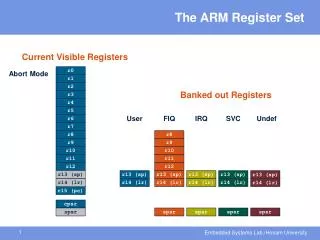
ARM programmer model • The state of an ARM system is determined by the content of visible registers and memory. • A user-mode program can see 15 32-bit general-purpose registers (R0-R14), program counter (PC) and CPSR. • Instruction set defines the operations that can change the state.
Memory system • Memory is a linear array of bytes addressed from 0 to 232-1 • Word, half-word, byte • Little-endian 0x00000000 0x00000001 0x00000002 0x00000003 0x00000004 0x00000005 0x00000006 0xFFFFFFFD 0xFFFFFFFE 0xFFFFFFFF
Byte ordering • Big Endian • Least significant byte has highest address Word address 0x00000000 Value: 00102030 • Little Endian • Least significant byte has lowest address Word address 0x00000000 Value: 30201000 0x00000000 0x00000001 0x00000002 0x00000003 0x00000004 0x00000005 0x00000006 0xFFFFFFFD 0xFFFFFFFE 0xFFFFFFFF
ARM programmer model 0x00000000 0x00000001 0x00000002 0x00000003 0x00000004 0x00000005 0x00000006 0xFFFFFFFD 0xFFFFFFFE 0xFFFFFFFF
Instruction set ARM instructions are all 32-bit long (except for Thumb mode). There are 232 possible machine instructions. Fortunately, they are structured.
Features of ARM instruction set • Load-store architecture • 3-address instructions • Conditional execution of every instruction • Possible to load/store multiple registers at once • Possible to combine shift and ALU operations in a single instruction
Instruction set • Data processing • Data movement • Flow control
Data processing • They are move, arithmetic, logical, comparison and multiply instructions. • Most data processing instructions can process one of their operands using the barrel shifter. • General rules: • All operands are 32-bit, coming from registers or literals. • The result, if any, is 32-bit and placed in a register (with the exception for long multiply which produces a 64-bit result) • 3-address format
Instruction set MOV<cc><S> Rd, <operands> MOVCS R0, R1 @ if carry is set @ then R0:=R1 MOVS R0, #0 @ R0:=0 @ Z=1, N=0 @ C, V unaffected
Conditional execution • Almost all ARM instructions have a condition field which allows it to be executed conditionally. movcs R0, R1
Register movement immediate,register,shift • MOV R0, R2 @ R0 = R2 • MVN R0, R2 @ R0 = ~R2 move negated
Addressing modes • Register operands ADD R0, R1, R2 • Immediate operands ADD R3, R3, #1 @ R3:=R3+1 AND R8, R7, #0xff @ R8=R7[7:0] a literal; most can be represented by (0..255)x22n 0<n<12 a hexadecimal literal This is assembler dependent syntax.
Shifted register operands • One operand to ALU is routed through the Barrel shifter. Thus, the operand can be modified before it is used. Useful for fast multipliation and dealing with lists, table and other complex data structure. (similar to the displacement addressing mode in CISC.) • Some instructions (e.g. MUL, CLZ, QADD) do not read barrel shifter.
Logical shift left MOV R0, R2, LSL #2 @ R0:=R2<<2 @ R2 unchanged Example: 0…0 0011 0000 Before R2=0x00000030 After R0=0x000000C0 R2=0x00000030 C register 0
C Logical shift right MOV R0, R2, LSR #2 @ R0:=R2>>2 @ R2 unchanged Example: 0…0 0011 0000 Before R2=0x00000030 After R0=0x0000000C R2=0x00000030 register 0
C Arithmetic shift right MOV R0, R2, ASR #2 @ R0:=R2>>2 @ R2 unchanged Example: 1010 0…0 0011 0000 Before R2=0xA0000030 After R0=0xE800000C R2=0xA0000030 register MSB
Rotate right MOV R0, R2, ROR #2 @ R0:=R2 rotate @ R2 unchanged Example: 0…0 0011 0001 Before R2=0x00000031 After R0=0x4000000C R2=0x00000031 register
C Rotate right extended MOV R0, R2, RRX @ R0:=R2 rotate @ R2 unchanged Example: 0…0 0011 0001 Before R2=0x00000031, C=1 After R0=0x80000018, C=1 R2=0x00000031 C register
Shifted register operands • It is possible to use a register to specify the number of bits to be shifted; only the bottom 8 bits of the register are significant. @ array index calculation ADD R0, R1, R2, LSL R3 @ R0:=R1+R2*2R3 @ fast multiply R2=35xR0 ADD R0, R0, R0, LSL #2 @ R0’=5xR0 RSB R2, R0, R0, LSL #3 @ R2 =7xR0’
Multiplication MOV R1, #35 MUL R2, R0, R1 or ADD R0, R0, R0, LSL #2 @ R0’=5xR0 RSB R2, R0, R0, LSL #3 @ R2 =7xR0’
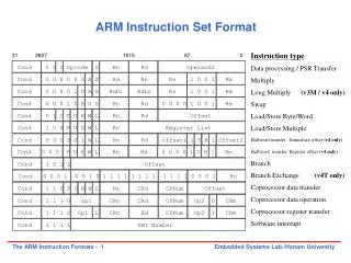
31 28 27 26 25 24 21 20 19 16 15 12 1 1 0 operand 2 cond 0 0 # opcode S Rn Rd destination register first operand register set condition codes arithmetic/logic function 25 1 1 8 7 0 #rot 8-bit immediate 1 immediate alignment 1 1 7 6 5 4 3 0 #shift Sh Rm 0 25 immediate shift length 0 shift type second operand register 1 1 8 7 6 5 4 3 0 Rs Sh Rm 0 1 register shift length Encoding data processing instructions
Arithmetic • Add and subtraction
-1 -128 127 0 3 -5 255 128 127 0 Arithmetic • ADD R0, R1, R2 @ R0 = R1+R2 • ADC R0, R1, R2 @ R0 = R1+R2+C • SUB R0, R1, R2 @ R0 = R1-R2 • SBC R0, R1, R2 @ R0 = R1-R2-!C • RSB R0, R1, R2 @ R0 = R2-R1 • RSC R0, R1, R2 @ R0 = R2-R1-!C 3-5=3+(-5) → sum<=255 →C=0 → borrow 5-3=5+(-3) → sum > 255 →C=1 → no borrow
Setting the condition codes • Any data processing instruction can set the condition codes if the programmers wish it to 64-bit addition ADDS R2, R2, R0 ADC R3, R3, R1 R1 R0 R3 R2 + R3 R2
Logical • AND R0, R1, R2 @ R0 = R1 and R2 • ORR R0, R1, R2 @ R0 = R1 or R2 • EOR R0, R1, R2 @ R0 = R1 xor R2 • BIC R0, R1, R2 @ R0 = R1 and (~R2) bit clear: R2 is a mask identifying which bits of R1 will be cleared to zero R1=0x11111111 R2=0x01100101 BIC R0, R1, R2 R0=0x10011010
Comparison • These instructions do not generate a result, but set condition code bits (N, Z, C, V) in CPSR. Often, a branch operation follows to change the program flow.
Comparison • CMP R1, R2 @ set cc on R1-R2 • CMN R1, R2 @ set cc on R1+R2 • TST R1, R2 @ set cc on R1 and R2 • TEQ R1, R2 @ set cc on R1 xor R2 compare compare negated bit test test equal
Multiplication • MUL R0, R1, R2 @ R0 = (R1xR2)[31:0] • Features: • Second operand can’t be immediate • The result register must be different from the first operand • Cycles depends on core type • If S bit is set, C flag is meaningless • See the reference manual (4.1.33)
Multiplication • Multiply-accumulate (2D array indexing) MLA R4, R3, R2, R1 @ R4 = R3xR2+R1 • Multiply with a constant can often be more efficiently implemented using shifted register operand MOV R1, #35 MUL R2, R0, R1 or ADD R0, R0, R0, LSL #2 @ R0’=5xR0 RSB R2, R0, R0, LSL #3 @ R2 =7xR0’
Flow control instructions • Determine the instruction to be executed next pc-relative offset within 32MB
Flow control instructions • Branch instruction B label … label: … • Conditional branches MOV R0, #0 loop: … ADD R0, R0, #1 CMP R0, #10 BNE loop
Branch and link • BL instruction save the return address to R14 (lr) BL sub @ call sub CMP R1, #5 @ return to here MOVEQ R1, #0 … sub: … @ sub entry point … MOV PC, LR @ return
Branch and link BL sub1 @ call sub1 … sub1: STMFD R13!, {R0-R2,R14} BL sub2 … LDMFD R13!, {R0-R2,PC} sub2: … … MOV PC, LR use stack to save/restore the return address and registers
Conditional execution CMP R0, #5 BEQ bypass @ if (R0!=5) { ADD R1, R1, R0 @ R1=R1+R0-R2 SUB R1, R1, R2 @ } bypass: … CMP R0, #5 ADDNE R1, R1, R0 SUBNE R1, R1, R2 smaller and faster Rule of thumb: if the conditional sequence is three instructions or less, it is better to use conditional executionthan a branch.