Download
1 / 27
270 likes | 345 Views
Progr ammable Logic Controller Internal Operations. Learning Objectives. This topic. covers the internal operations of a PLC illustrates the concept of scan time explains I/O response time discusses practical issues of input signal interface with PLC

E N D
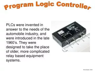
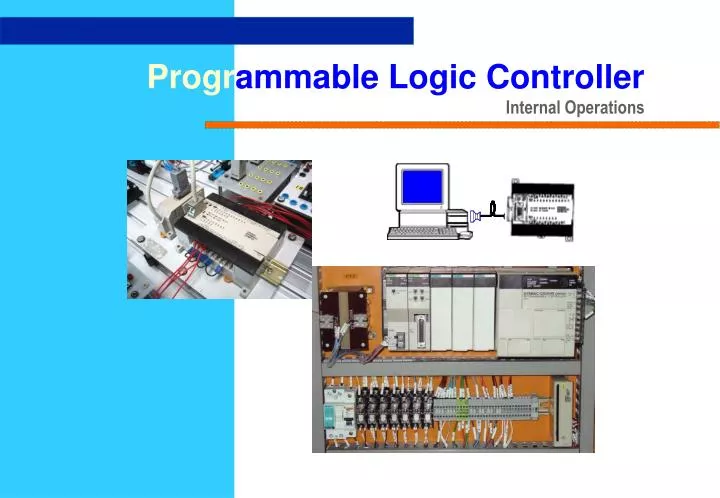
Programmable Logic Controller Internal Operations
Learning Objectives This topic • covers the internal operations of a PLC • illustrates the concept of scan time • explains I/O response time • discusses practical issues of input signal interface with PLC • discusses practical issues of output signal interface with PLC Chapter PLC3
Applications of PLCs: • Sequence control • Motion Control • Process Control • Field bus • Communication • Data Management Chapter PLC3
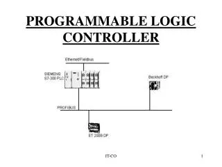
Internal Operation of PLCs:Input / Output Addressing Chapter PLC3
000.00 010.01 Internal Operation of PLCs:Input / Output Addressing INPUT OUTPUT PROGRAM Chapter PLC3
INPUT OUTPUT 000.00 010.01 PROGRAM Internal Operation of PLCs:Input / Output Addressing Executes Program Reads Input Sets Output Chapter PLC3
Executes Program Reads Input On Output Stores Output Status at Output RAM Turns on Output Executes Program Reads All Input Status Updates Status at Input RAM Transfer to Output Module read one at a time Input / Output Addressing Input / Output Processing Most common method is mass input/output copying Decides which Outputs to turn on • These outputs are latched and they retain their status until they are updated by the next I/O copying routine. Chapter PLC3
Copy all inputs into RAM Fetch, decode and execute all instructions in sequence Copy all outputs from O/P RAM to output unit and input all inputs to I/P RAM Time depends on length of total program e.g. 1K program = 5 ms Fixed length delay e.g.5 ms Program Execution I/O Copy End I/O Copy START Program I/O Refresh • The process of writing from RAM to the output relays and reading input relay status to RAM is known as I/O Refresh. I/O Refresh. Chapter PLC3
Sets Output Reads Input Executes Program • Data input and outputwhen status of the input relays will be written into the input portion of the I/O RAM and status of the output portion will be reflected in the output relays. • Instruction executionwhich includes an executive routine in which the base intelligence of the system is used to interpret the user program containing the instructions to be executed. • Common processes, such as watchdog timer resetting, checking the I/O bus, checking scan time, diagnostic operations and housekeeping on program memory – processes. Communication windows which include the link service of a host computer and communications with peripheral devices. Scan Time On power up, CPU goes through a series of internal processes Chapter PLC3
Sets Output Sets Output Reads Input Reads Input Executes Program Executes Program Scan Time One Scan One Scan • Scan time is the total time required for PLC to perform activities in each scan cycle. • Typical scan time for 500 instruction words varies between 3 ms and 10 ms with ladder logic programming. Chapter PLC3
One Scan One Scan Sets Output Sets Output Reads Input Reads Input Executes Program Executes Program Scan Time Case 1 : And DETECTED !! INPUT SIGNAL comes in ….. Chapter PLC3
One Scan One Scan Sets Output Sets Output Reads Input Reads Input Executes Program Executes Program Scan Time Case 2 : No INPUT SIGNAL comes in ….. Some INPUT SIGNAL comes in ….. And DETECT nothing !! And DETECTED !! Chapter PLC3
One Scan One Scan Sets Output Sets Output Reads Input Reads Input Executes Program Executes Program Scan Time Case 3 : And NOTDETECTED !! INPUT SIGNAL comes in ….. Because of the cyclic nature of I/O copying routine, input signals of high frequency which change state after the READ routine will not be recognised until the next copy occurs. Only certain PLCs incorporate a subroutine to interrupt the scan to pick up such signals. Chapter PLC3
Mechanical DC proximity AC/DC Switches sensors 2 - wire or Proximity sensors ‘Dry Contacts’ 24V DC Load 1 COM 2 NC +24V DC +24V + 3 NO + 4 source L oad 24V 5 Load sink - - ( - ) ( - ) Interfacing On-Off Sensors with PLCs Sensors solid state output relay output PNP NPN Chapter PLC3
solid state output PNP NPN +24V DC +24V + + source L oad Load sink - - ( - ) ( - ) Interfacing On-Off Sensors with PLCs Input Cards can be broadly classified into two categories: a) source type (or common positive), & b) sink type (or common negative). NPN (current sinking) sensor must be matched with a source type input card. PNP (current sourcing) sensor must be matched with a Sinking type input card. Chapter PLC3
When Sensor is ON… Signal is detected Interfacing On-Off Sensors with PLCs:Input Units and Interface Circuits NPN (current sinking) sensor must be matched with a source type input card. PLC Sources When Sensor is OFF… SENSOR Sinks No Signal Chapter PLC3
When Sensor is ON… Interfacing On-Off Sensors with PLCs:Input Units and Interface Circuits PNP (current sourcing) sensor must be matched with a Sinking type input card. PLC Sinks SENSOR Souces Chapter PLC3
Power Supply Interfacing On-Off Loads with PLCs Output Module of PLCs are used to drive loads, such as • solenoids, • lights, • buzzers, • motor contactors, etc Output Module Output Module These loads are powered by an External Power Source not within the PLC. Chapter PLC3
Types of Output Modules Transisterised npn pnp Relay Triac Chapter PLC3
AC/ DC 2A Typical 10ms Typical AC 1A Typical 3ms Typical DC 1A Typical 1ms Typical Interfacing On-Off Loads with PLCs Factors affecting selection of Output Module: Characteristics Type of Output Chapter PLC3
Interfacing On-Off Loads with PLCs Transisterised NPN Type LOAD + - Chapter PLC3
Interfacing On-Off Loads with PLCs Transisterised PNP Type LOAD Chapter PLC3
Interfacing On-Off Loads with PLCs Triac Type LOAD Chapter PLC3
Interfacing On-Off Loads with PLCs Relay Type LOAD Chapter PLC3
Interfacing On-Off Loads with PLCs Relay Type LOAD Chapter PLC3
Interfacing On-Off Loads with PLCs Relay Type LOAD Chapter PLC3
Summary This chapter: • covers the internal operations of a Programmable Controller • illustrates the concept of scan time • explains I/O response time • discusses practical issues of input signal interface with Programmable Controller • discusses practical issues of output signal interface with Programmable Controller Chapter PLC3