Download
1 / 50
810 likes | 1.64k Views
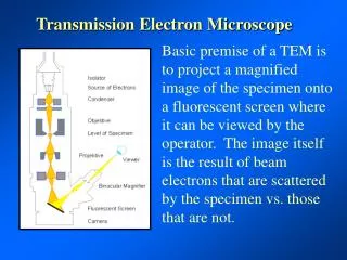
The transmission electron microscope. Additional web resources. http://nanohub.org/resources/3777 Eric Stach (2008), ”MSE 528 Lecture 4: The instrument, Part 1, http://nanohub.org/resources/3907. 3,8 Å. 1,1 nm. Simplified ray diagram. Parallel incoming electron beam. Si. Sample.

E N D
Additional web resources • http://nanohub.org/resources/3777 • Eric Stach (2008), ”MSE 528 Lecture 4: The instrument, Part 1, http://nanohub.org/resources/3907
3,8 Å 1,1 nm Simplified ray diagram Parallel incoming electron beam Si Sample Objective lense Diffraction plane (back focal plane) Objective aperture Selected area aperture Image plane MENA3100 V08
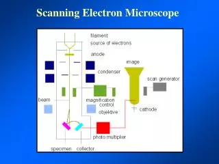
JEOL 2000FX • Wehnelt cylinder • Filament • Anode • Electron gun 1. and 2. beam deflectors • and 2. condenser lens • Condenser aperture • Condenser lens stigmator coils • Condenser lens 1. and 2. beam deflector • Condenser mini-lens • Objective lens pole piece • Objective aperture • Objective lens pole piece • Objective lens stigmators • Image shift coils • Objective mini-lens coils (low mag) • 2. Image shift coils • 1., 2.and 3. Intermediate lens • Projector lens beam deflectors • Projector lens • Screen Electron gun Illumination system Mini-lens screws Specimen Intermediate lens shifting screws Projector lens shifting screws
Eric Stach (2008), ”MSE 528 Lecture 4: The instrument, Part 1, http://nanohub.org/resources/3907
Eric Stach (2008), ”MSE 528 Lecture 4: The instrument, Part 1, http://nanohub.org/resources/3907
The requirements of the illumination system • High electron intensity • Image visible at high magnifications • Small energy spread • Reduce chromatic aberrations effect in obj. lens • Adequate working space between the illumination system and the specimen • High brightness of the electron beam • Reduce spherical aberration effects in the obj. lens
The electron gun • The performance of the gun is characterised by: • Beam diameter, dcr • Divergence angle, αcr • Beam current, Icr • Beam brightness, βcr at the cross over d Cross over α Image of source
Brightness • Brightness is the current density per unit solid angle of the source • β = ie/(πdcαc)2 d Cross over α Image of source
The electron source • Two types of emission sources • Thermionic emission • W or LaB6 • Field emission • W ZnO/W Cold FEG Schottky FEG
The electron gun Thermionic gun FEG Bias -200 V Wehnelt cylinder Cathode -200 kV Anode Ground potential Equipotential lines dcr Cross over αcr
Thermionic guns • Filament heated to give • Thermionic emission • Directly (W) or • indirectly (LaB6) • Filament negative • potential to ground • Wehnelt produces a • small negative bias • Brings electrons to • cross over
Thermionic emission • Current density: • Ac: Richardson’s constant, material dependent • T: Operating temperature (K) • φ: Work function (natural barrier that prevents electrons from leaving the solid) • k: Boltzmann’s constant Jc= AcT2exp(-φc/kT) Richardson-Dushman Maximum usable temperature T is determined by the onset of the melting/evaporation of material.
Field emission • Current density: Fowler-Norheim Maxwell-Boltzmann energydistribution for all sources
Field emission • The principle: • The strength of an electric field E is considerably increased at sharp points. E=V/r • rW < 0.1 µm, V=1 kV → E = 1010 V/m • Lowers the work-function barrier so that electrons can tunnel out of the tungsten. • Surface has to be pristine (no contamination or oxide) • Ultra high vacuum condition (Cold FEG) or poorer vacuum if tip is heated (”thermal” FE; ZrO surface tratments → Schottky emitters).
Characteristics of principal electron sources at 200 kV * Might be one order lower
Advantages and disadvantages of the different electron sources
Electron lenses Any axially symmetrical electric or magnetic field has the properties of an ideal lens for paraxial rays of charged particles. • Electrostatic • Require high voltage - insulation problems • Not used as imaging lenses, but are used in modern monochromators or deflectors • Magnetic • Can be made more accurately • Shorter focal length F= -eE F= -e(v x B)
General features of magnetic lenses • Focuses near-axis electron rays with the same accuracy as a glass lens focuses near axis light rays. • Same aberrations as glass lenses. • Converging lenses. • The bore of the pole pieces in an objective lens is about 4 mm or less. • A single magnetic lens rotates the image relative to the object. • Focal length can be varied by changing the field between the pole pieces (changing magnification). http://www.matter.org.uk/tem/lenses/electromagnetic_lenses.htm
Electromagnetic lens Bore Soft Fe pole piece Current in the coil creates A magnetic field in the bore. The magnetic field has axial symmetry, but is inhomogenious along the length of the lens. gap Cu coil The soft iron core can increase the field by several thousand times.
Electron ray paths through magnetic fields B r The electron spirals through the lens field: A helical trajectory. For electrons with higher keV, we must use stronger lenses (larger B) to get similar ray paths. θ v v2 v1 See fig 6.9
Simple ray diagrams • Electron lenses act like a convex glas lens • Thin lens • β: variable giving the fraction of rays collected by the lens ~ 10 m rad ~0.57o Point obj β α Point image Never a perfect image
Changing the strength of the lens • The further away rays are from the optical axis the stronger they are bent by a convex lens. • What happens to the focal and image plane when the strength of the lens is changed? • What happens to the image?
The strength of the lens • Under conditions normally found in the TEM, strong lenses magnify less and demagnify more (not in VLM). • When do we want to demagnify an object?
r2 r1 α Plane of least confusion Spherical aberration Gaussian image plane Highest intensity in the Gaussian image plane ds = 0.5MCsα3 (disk diameter, plane of least confusion) ds = 2MCsα3 (disk diameter, Gaussian image plane) M: magnification Cs :Spherical aberration coefficient α: angular aperture/ angular deviation from optical axis 2000FX: Cs= 2.3 mm 2010F: Cs= 0.5 nm
v v - Δv Chromatic aberration Diameter for disk of least confusion: dc = Ccα ((ΔU/U)2+ (2ΔI/I)2 + (ΔE/E)2)0.5 Cc: Chromatic aberration coefficient α: angular divergence of the beam U: acceleration voltage I: Current in the windings of the objective lens E: Energy of the electrons 2000FX: Cc= 2.2 mm 2010F: Cc= 1.0 mm Disk of least confusion Thermally emitted electrons: ΔE/E=kT/eU, LaB6: ~1 eV The specimenwillintroducechromaticaberration. The thinner thespecimenthebetter!! Correcting for Cc effects only makes sense if you are dealing with specimens that are thin enough.
Loss of axial symmetry x y-focus y x-focus Lens astigmatism Due to non-uniform magnetic field as in the case of non-cylindrical lenses. Apertures may affect the beam if not precisely centered around the axis. This astigmatism can not be prevented, but it can be corrected! Disk of least confusion Diameter of disk of least confusion: da: Δfα
Depth of focus and depth of field (image) • Imperfections in the lenses limit the resolution but give a better depth of focus and depth of image. • Use of small apertures to minimize aberrations. • The depth of field (Δb or Dob) is measured at, and refers to, the object. • Distance along the axis on both sides of the object plane within which the object can move without detectable loss of focus in the image. • The depth of focus (Δa, or Dim), is measured in, and referes to, the image plane. • Distance along the axis on both sides of the image plane within which the image appears focused.
αim Depthoffocus and depthoffield (image) 1 1 dob 2 dim 2 βob Dim Dob Ray 1 and 2 represent the extremes of the ray paths that remain in focus when emerging ± Dob/2 either side of a plane of the specimen. αim≈ tan αim= (dim/2)/(Dob/2) βob≈ tan βob= (dob/2)/(Dim/2) Angular magnification: MA= αim/ βob Transvers magnification: MT=dim/dob MT=1/MA Depth of focus: Dim=(dob/ βob)MT2 Depth of field: Dob=dob/ βob
Depth of field Depth of field: Dob=dob/ βob Carefull selection of βob • Thin sample: βob ~10-4 rad • Thicker, more strongly scattering specimen: βob (defined by obj. aperture) ~10-2 rad Example: dob/ βob= 0.2 nm/10 mrad = 20 nm Dob= thicknessofsample all in focus Example: dob/ βob= 2 nm/10 mrad = 200 nm
Depth of focus Depth of focus: Dim=(dob/ βob)MT2 Example: To see a feature of 0.2 nm you would use a magnification of ~500.000 x (dob/ βob)M2= 20 nm *(5*105)2= 5 km Example: To see a feature of 2 nm you would use a magnification of ~50.000 x (dob/ βob)M2= 200 nm *(5*104)2= 500 m Focusonthewieving screen and far below!
Fraunhofer and Fresnel diffraction • Fraunhofer diffraction: far-field diffraction • The electron source and the screen are at infinite distance from the diffracting specimen. • Flat wavefront • Fresnel diffraction: near-field diffraction • Either one or both (electron source and screen) distances are finite. Electrondiffractionpatternscorrespondclosely to theFraunhofer case whilewe ”see” theeffectofFresneldiffraction in our images.
Airy discs (rings) • Fraunhofer diffraction from a circular aperture will give a series of concentric rings with intensity I given by: I(u)=Io(JI(πu)/ πu)2 http://en.wikipedia.org/wiki/Airy_disk
Strengths of lenses and focused image of the source http://www.rodenburg.org/guide/t300.html If you turn up one lens (i.e. make it stronger, or ‘over- focus’ then you must turn the other lens down (i.e. make it weaker, or ‘under-focus’ it, or turn its knob anti-clockwise) to keep the image in focus.
Magnification of image, Rays from different parts of the object http://www.rodenburg.org/guide/t300.html If the strengths (excitations) of the two lenses are changed, the magnification of the image changes
The Objective lens • Often a double or twin lens • The most important lens • Determines the resolving power of the TEM • All the aberations of the objective lens are magnified by the intermediate and projector lens. • The most important aberrations • Astigmatism • Spherical • Chromatic
Astigmatism Can be corrected for with stigmators
The objective lens • Cs can be calculated from information about the shape of the magnetic field • Cs has ~ the same value as the focal length (see table 2.3) • The objective lens is made as strong as possible • Limitation on the strength of a magnetic lens with an iron core (saturation of the magnetization Ms) • Superconductiong lenses (give a fixed field, but need liquid helium cooling)
Apertures We use apertures in the lenses to control the divergence or convergence of electron paths through the lens which, in turn, affects the lens aberrations and controls the current in the beam hitting the sample.
Use of apertures Condenser apertures: Limit the beam divergence (reducing the diameter of the discs in the convergent electron diffraction pattern). Limit the number of electrons hitting the sample (reducing the intensity). Objective apertures: Control the contrast in the image. Allow certain reflections to contribute to the image. Bright field imaging (central beam, 000), Dark field imaging (one reflection, g), High resolution Images (several reflections from a zone axis). MENA3100 V08
Objective aperture BF image Objective aperture: Contrast enhancement Bright field (BF) glue (light elements) hole Ag and Pb Si All electrons contribute to the image. Only central beam contributes to the image.
Objective aperture BF image Weak-beam DF image Small objective apertureBright field (BF), dark field (DF) and weak-beam (WB) Diffraction contrast Dissociation of pure screw dislocation In Ni3Al, Meng and Preston, J. Mater. Scicence, 35, p. 821-828, 2000.
HREM image Large objective aperture High Resolution Electron Microscopy (HREM) Phase contrast
Use of apertures Condenser aperture: It limits the beam divergence (reducing the diameter of the discs in the convergent electron diffraction pattern). It limits the number of electrons hitting the sample (reducing the intensity). Objective aperture: It controls the contrast in the image. It allows certain reflections to contribute to the image. Bright field imaging (central beam, 000), Dark field imaging (one reflection, g), high resolution images (several reflections from a zone axis). Selected area aperture: It selects diffraction patterns from small (> 1µm) areas of the specimen. It allows only electrons going through an area on the sample that is limited by the SAD aperture to contribute to the diffraction pattern (SAD pattern).
Selected area diffraction Parallel incoming electron beam Specimen with two crystals (red and blue) Objective lense Pattern on the screen Diffraction pattern Selected area aperture Image plane
Diffraction with no aperturesConvergent beam and Micro diffraction (CBED and µ-diffraction) Convergent beam Illuminated area less than the SAD aperture size. Convergent beam Focused beam C2 lens Small probe CBED pattern µ-diffraction pattern Diffraction information from an area with ~ same thickness and crystal orientation
Shadow imaging (diffraction mode) Parallel incoming electron beam Sample Objective lense Diffraction plane (back focal plane) Image plane
Magnification and calibration Resolution of the photographic emulsion: 20-50 µm Magnification depends on specimen position in the objective lens Magnification higher than 100 000x can be calibrated by using lattice images. Rotation of images in the TEM.