Download
1 / 58
580 likes | 588 Views
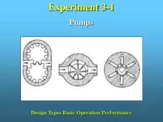
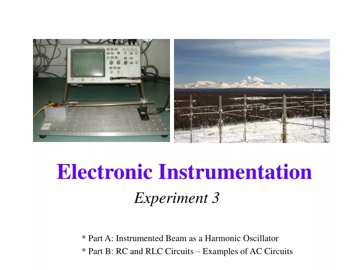
Experiment 3. * Part A: Instrumented Beam as a Harmonic Oscillator * Part B: RC and RLC Circuits – Examples of AC Circuits. Part A. Harmonic Oscillators Analysis of Cantilever Beam Frequency Measurements. Macroscopic Examples of Harmonic Oscillators. Spring-mass combination Violin string

E N D
Experiment 3 * Part A: Instrumented Beam as a Harmonic Oscillator * Part B: RC and RLC Circuits – Examples of AC Circuits
Part A • Harmonic Oscillators • Analysis of Cantilever Beam Frequency Measurements 2
Macroscopic Examples of Harmonic Oscillators • Spring-mass combination • Violin string • Wind instrument • Clock pendulum • Playground swing • LC or RLC circuits • Others? 3
Large Scale Examples • Petronas (452m) and CN (553m) Towers 4
Harmonic Oscillator • Equation • Solution x = Asin(ωt) • x is the displacement of the oscillator while A is the amplitude of the displacement 5
Spring • Spring Force F = ma = -kx • Oscillation Frequency • This expression for frequency hold for a massless spring with a mass at the end, as shown in the diagram. 6
Spring Model for the Cantilever Beam • Where l is the length, t is the thickness, w is the width, and mbeam is the mass of the beam. Where mweight is the applied mass and a is the length to the location of the applied mass. 7
Spring Model -- Continued • For a beam loaded with a mass at the end, a is equal to l. For this case: where E is Young’s modulus of the beam. • Since real beams have finite mass, it is necessary to use the equivalent mass at the end that would produce the same frequency response. This is 0.23mbeam. 8
Spring Model -- Continued • Now we can apply the expression for the ideal spring mass frequency to the beam. • Where the mass used now is given by 9
Atomic Force Microscopy -AFM • This is one of the key instruments driving the nanotechnology revolution • Dynamic mode uses frequency to extract force information Note Strain Gage 10
AFM on Mars • Redundancy is built into the AFM so that the tips can be replaced remotely. 11
AFM on Mars • Soil is scooped up by robot arm and placed on sample. Sample wheel rotates to scan head. Scan is made and image is stored. 12
AFM Image of Human Chromosomes • There are other ways to measure deflection. 13
AFM Optical Pickup • On the left is the generic picture of the beam. On the right is the optical sensor. 14
Our Experiment • For our beam, we must deal with the beam mass, the extra mass of the magnet and its holder (for the magnetic pick up coil), and any extra load we add to the beam to observe how its performance depends on load conditions. 15
Our Experiment • For simplicity, call m the combination of 0.23 times the beam mass plus the magnet and its holder. • To obtain a good measure of k and m, we will make 4 measurements of oscillation frequency using 3 extra masses. 16
Our Experiment • We will then have 4 equations and 2 unknowns. • One we obtain values for k and m we can plot to see how we did. 17
Our Experiment • One method is to guess values for k and m and then keep adjusting them until we obtain a good fit, obtaining something like: 18
Our Experiment • How to guess values for k and m? • Estimate the mass by measuring the beam dimensions and assuming the beam, magnet and holder are made from something reasonable. • Use your guess for m with your largest load mass to obtain a guess for k. • Plot f as a function of load mass • Change values of k and m until your function and data match. 19
Magnet Our Experiment • Can you think of other ways to more systematically determine k and m? • Experimental hint: make sure you keep the center of any mass you add as near to the end of the beam as possible. It can be to the side, but not in front or behind the end. C-Clamp 20
MEMS Accelerometer • An array of cantilever beams can be constructed at very small scale to act as accelerometers. Note Scale 21
Hard Drive Cantilever • The read-write head is at the end of a cantilever. This control problem is a remarkable feat of engineering. 25
More on Hard Drives • A great example of Mechatronics. 26
Modeling Damped Oscillations • v(t) = A sin(ωt) 27
Modeling Damped Oscillations • v(t) = Be-αt 28
Modeling Damped Oscillations • v(t) = A sin(ωt) Be-αt = Ce-αtsin(ωt) 29
Finding the Damping Constant • Choose two maxima at extreme ends of the decay. 30
Finding the Damping Constant • Assume (t0,v0) is the starting point for the decay. • The amplitude at this point,v0, is C. • v(t) = Ce-αtsin(ωt) at (t1,v1): v1 = v0e-α(t1-t0)sin(π/2) = v0e-α(t1-t0) • Substitute and solve for α: v1 = v0e-α(t1-t0) 31
Part B • LC and RLC Circuits • Intro to AC Circuits 32
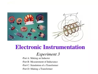
Inductors • An inductor is a coil of wire through which a current is passed. The current can be either AC or DC. 33
Inductors • This generates a magnetic field, which induces a voltage proportional to the rate of change of the current. 34
Inductors • Inductors are also electromagnets. • The magnetic field produced by the inductor current can do work. • There is, therefore, energy stored in the magnetic field of the inductor. 35
Combining Inductors • Inductances add like resistances • Series • Parallel 36
frequency frequency approaches impedance approaches looks like called low zero zero short circuit high infinity infinity open circuit Inductor Impedance • Note that this behavior is exactly the opposite of capacitors. 37
Filters • Even simple circuits can pass some frequencies and reject others. Thus, by selecting the right kind of circuit, certain frequencies can be filtered out. 38
Spring-Mass W = KE + PE KE = kinetic energy=½mv² PE = potential energy(spring)=½kx² W = ½mv² + ½kx² Electronics W = LE + CE LE = inductor energy=½LI² CE = capacitor energy=½CV² W = ½LI² + ½CV² Oscillator Analysis 39
Take the time derivative Take the time derivative Oscillator Analysis 40
W is a constant. Therefore, Also W is a constant. Therefore, Also Oscillator Analysis 41
Simplify Simplify Oscillator Analysis 42
Solution Solution Oscillator Analysis Vc= Asin(ωt) x = Asin(ωt) 43
Using Conservation Laws • Please also see the write up for Experiment 3 for how to use energy conservation to derive the equations of motion for the beam and voltage and current relationships for inductors and capacitors. • Almost everything useful we know can be derived from some kind of conservation law. 44
Thevenin Voltage Equivalents+ • Recall that the function generator (aka waveform generator) has an internal impedance of 50 Ohms. Thus, the circuit representation of this device looks like: +Required for HW #3 45
Thevenin • Such a simple combination of a voltage source and resistance is called a Thevenin source. • It is generally possible to simplify any complex source into such a combination. • In fact, the function generator is much more complex, but it can be most simply represented this way. 46
Thevenin • Example Load Resistor 47
Thevenin • We might also see a circuit with no load resistor, like the voltage divider. 48
Thevenin Method A • Find Vth (open circuit voltage) • Remove load if there is one so that load is open • Find voltage across the open load • Find Rth (Thevenin resistance) • Set voltage sources to zero (current sources to open) – in effect, shut off the sources • Find equivalent resistance from A to B B 49
Thevenin Method Example • Remove Load A B A B 50