Download
1 / 45
450 likes | 626 Views
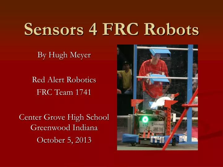
Sensors 4 FRC Robots. By Hugh Meyer Red Alert Robotics FRC Team 1741 Center Grove High School Greenwood Indiana October 5, 2013. Why Do We Need Sensors?. Protect robot from self destruction Protect robot from driver destruction Provide closed loop control Sense position

E N D
Sensors 4 FRC Robots By Hugh Meyer Red Alert Robotics FRC Team 1741 Center Grove High School Greenwood Indiana October 5, 2013
Why Do We Need Sensors? • Protect robot from self destruction • Protect robot from driver destruction • Provide closed loop control • Sense position • Feedback for autonomous mode • Limit range of motion • Confirmation system is functioning properly • Gives electrical team something to do
Mechanical Limit Switches • Lever or roller actuated • Several sizes available • VR7 is popular, easy to work with, inexpensive, supplied in kit of parts • Simple to wire – connect red and black wires to NC and NO connections, connect white signal wire to the COM connection • Orient the lever so it wipes across the cam – Avoid having the switch become your mechanical limit
Mechanical Limit Switches • Signal is on/off or true/false or 1/0 • Connected to digital I/O on the Digital Side Car • Software reads a one or zero • Switch connections will be labeled
Mechanical Limit Switches • Common • Normally Closed • Normally Open • Common terminal is the output • NO and NC would be ground and + 5 volts
Magnetic Reed Switches • High reliability – Reed contacts are sealed in a small glass cylinder • Easy to wire – Connect one terminal to the black wire and the other to the white wire • Used on Pneumatic cylinders, but the cylinder must be ordered with the magnetic ring option • Magnet is the element in motion to be sensed by the reed switch
Fixed Pressure Switch • Used to control air compressor • Switch closes when pressure is below a predefined low limit value and opens when pressure is above a high limit value • Simple to wire – Black and white wire connect to the switch
Pressure Transmitter • Provides an analog or digital signal indicating the exact pressure • Analog wiring is simplest – Black and red wires supply power to sensor and the white connects to the analog input • Digital device will connect to a SPI, I2C, or serial port
Push Buttons • Momentary contact • Suggest connecting all three wires – Black and red to NC & NO contacts and white wire to the COM contact • Available in many different sizes, shapes, color, and styles • Driver station ultimate control
Toggle Switches • Generally not momentary action – switch stays at position when released • Available in many different contact arrangements • FRC usage can generally use the simple SPDT (single pole double throw) • Center off is available if appropriate
Quadrature Encoders • Measures speed, distance, and position • Signal can return to the cRIO or Jaguar, or both • Requires two digital inputs if you want directional information and highest resolution • Signals are 90 degrees out of phase
Quadrature Encoders • Different sizes available • Several styles available • Kit of parts encoders must be installed carefully • Encoder disk must be correct distance from optical element • Need oscilloscope to verify correct operation
Quadrature Encoders • Available in different resolutions • The line count specifies the resolution • Higher count gives the I and D components of PID faster information for better response • Lower count is more tolerant of alignment errors • Several functions in WPILib are available depending if you want speed or distance • Incremental device – If you want absolute position then you need to home the system, or always start from a known position
Potentiometer Absolute Encoder • Always know where you are • Standard pot supports up to 270 degrees of rotation • Multi-turn pots can support more than one rotation • Home switch and sequence not required • Analog voltage output is proportional to position • Black and red wires go to outer connections on pot • Signal comes from the wiper terminal
Absolute Magnetic Shaft Encoder • Similar to a single turn pot, but allows full 360 degree rotation with no stops • Available with an analog or a pulse width modulated digital output • Output signal is proportional to the absolute shaft position • Different bearing configurations are offered • Can be used as operator control as well as sensor on robot • Connected to analog bumper on analog I/O module
Rotary Magnetic Encoder • No mechanical contact • Accurate alignment is important • Data sheet is on KOP webpage • Several IO options
Linear Motion Magnetic Encoder • No mechanical contact • Accurate alignment is important • Data sheet is on KOP webpage • Several IO options • Quad outputs
Linear Motion Optical Encoder • High precision • Any length encoder strip • Quad output • US Digital • Resolution of sensor and strip must match • Includes index mark for home position
Gear Tooth Encoder • Alignment not critical • Works with steel chain sprockets or gears • Pulse width modulated output • WPI Library has a function to read these type of sensors
Ultrasonic Distance Sensor • Measures distance to a target • Two styles of sensors available – Dual element and single element • Available with analog or digital outputs • Digital output would be the preferred method • Good for localization for autonomous mode • Sensitively spec is used for scaling voltage data to feet or inches • Get that information from the data sheet
Gyro - Inertial Turn Rate Sensor • Measures the rate of turn • Can be used for heading data for autonomous drive mode • Can be used to create a field oriented style drive scheme • Can be used to create a target oriented style drive scheme • If oriented properly can be a tilt sensor, although the accelerometer can do that naturally with the Z axis data
Inertial Accelerometer Sensor • Measures rate of change in motion and the direction of gravity • Three axis sensor – X, Y, Z • Z axis measures direction of gravity and can be used as a tilt sensor • X axis, if oriented properly, will measure forward and backward motion • Y axis, if oriented properly, will measure sideways motion
Inertial Sensor • Should be mounted on a mass that is suspended in foam • This acts as a low pass filter and will significantly reduce high frequency noise • Accelerometer output is available in digital or analog outputs • Analog outputs require one analog input for each axis • Digital outputs require four digital I/O connections on the digital side car • Use the SPI interface software functions to get the data • Use the digital outputs – This prevents the bias from becoming an issue
Inertial Sensor • Rate gyro output is available as an analog output • Connect this output to the analog bumper input • Use shielded wire for a clean signal • System must measure the bias when the sensor is initialized • System must be absolutely stationary when the system is measuring the bias • If your gyro is drifting it is likely because the system was in motion during the initialization period
Inertial Sensor • If you have a onboard air compressor it should not run during the gyro bias measurement time • Sensitivity must be passed to the gyro class when it is initialized • Sensitively is found on the data sheet for the device • Accelerometer sensitivity will be on the order of 300 mV/g • Gyro sensitivity will be on the order of 7 mV/degrees/s • Read the data sheet provided by FIRST and the data sheet from the manufacturer • The FPGA in the cRIO does the integration for you to get an angle
Inertial Sensors More Information • Kevin Watson has some good information about these types of sensors • He has some well commented code if you really want to get into the details • http://kevin.org • The FPGA in the cRIO really does the hard work integrating the gyro rate data to get an angle
Optical Transmitted Beam • Consists of two elements – a transmitter and a receiver • A signal is output when the light beam is blocked • Alignment is important • Simple packaging is readily available off the shelf • Power must be supplied to both the TX and RX
Optical Transmitted Beam • Use a regulated power output. Most require 24 volts which you can get using the solenoid bumper wired to the 24 volt supply • Detected object must be large enough for the sensor to see
Optical Retro Reflective • Uses a retro reflective target • Only one device • Target can be a flag in motion • Target can be stationary and have an opaque flag block the light – The flag must not be reflective, or it will be detected
Optical Vane Transmitted Beam • One piece housing in a U shape – also called slot sensor • Available in several different sizes • Will detect presence of any opaque object that is inserted into the U • Very effective for home sensors when used with incremental encoders • No mechanical contact for high reliability • Simple to actuate • Does not require precise alignment or mounting
LED & Photo Transistor • Roll your own for a fraction of the cost • Flexible designing package since you make your own • LED (LTE-4208) and Photo transistor (LTR-3208E) must be a matched pair • IR light is best because that will reduce the effect of ambient light • Works over a wide distance range
LED & Photo Transistor • Requires resistors in the circuit to work properly • LED needs a current limiting resistor in series with it to drop the 5 volts down to 1.2~1.6 volts • Size this resistor to draw 15 ~ 30 milliamps • Check the spec sheet for the target current • A good range will be 180 ~ 221 ohms if using a 5 volt power supply, I used 221 ohms for this device • You can calculate the value or measure it if you have an ammeter
LED & Photo Transistor • Photo transistor needs a pull up or down resistor depending on the wiring scheme you select • A good range will be 2k ~ 4k ohm, I used 3.16k for this device • Resistor can be above the transistor or below it • Above you get a high when the light beam is blocked • Below you get a low when the light beam is blocked
LED & Photo Transistor • R = 221 ohms • RL = 3.16k ohms
Current Sensor • Measures current flowing to a motor • Indicates if the motor is running within load specifications • Helps prevent “magic smoke” from exiting the motor • Hal effect sensors can measure DC current • IC based sensors can be inserted into the circuit • Jaguar speed controllers have current measuring ability built right in – you just need to ask it
Test Rig • Always measure motor current when building proto types • 12” piece of 10 AWG wire makes a good shunt resistor • 1 milli-volt equals 1 amp current flow
Cameras • Two types provided over the years from the kit of parts • Axis M1011 • Axis 206 • Any others are legal if they are IP based • Library provided by FIRST is very advance • Several teams got vision to work for them • Can be connected directly to the cRIO or radio • Vision processing can be done on cRIO or driver station
Tools Needed • Oscilloscope is very helpful • Voltmeter • Ammeter • Soldering Equipment • Connectors • Shielded wire
Software You Need to Write • Code that will read the sensor • Code that will log the data from the sensor • First thing you should do is hook up sensors you plan to use and start reading data • Don’t wait • Connect sensors and start reading data as soon as possible!!
Log The Data • Log the data to a file on the cRIO • Send the data to the driver station and log to a file on the DS • Add external device that logs to a memory card • Logomatic by Spark Fun Electronics • https://www.sparkfun.com/products/10216
Sensor Guidelines • It always needs a sensor • If a mechanism has limited travel then it needs an end of travel (EOT) limit sensor on both ends! • Start reading data from sensors as soon as you can so you will learn what is required and the type of data • Design your sensors into the system. Add on after thought mounting schemes tend to be unreliable
Kit of Parts Sensors • Use the resources provided by FIRST at the kit of parts website • They have data sheets and instructions specific to our application • http://www.usfirst.org/roboticsprograms/frc/2012-kit-of-parts-sensors
Suppliers • AndyMark - http://www.andymark.com/Default.asp • US Digital - http://usdigital.com/ • Digikey - http://www.digikey.com/ • Mouser Electronics - http://www.mouser.com/ • Newark Electronics - http://www.newark.com/ • Allied Electronics - http://www.alliedelec.com/ • Rockwell Automation - http://www.ab.com/catalogs/ • Automation Direct - http://www.automationdirect.com/adc/Shopping/Catalog/Sensors_-z-_Encoders • Spark Fun Electronics - http://www.sparkfun.com/ • Parallax Inc. - http://www.parallax.com/tabid/768/ProductID/92/Default.aspx • MaxBotix - http://www.maxbotix.com/ • Suzo Happ - http://na.suzohapp.com/pushbuttons/pushbuttons.htm • Penny+Giles - http://www.pennyandgiles.com/Joystick-Controllers-pg-28,2,,.php • State Electronics - http://www.potentiometers.com/select_joystick.cfm
Questions • Hugh Meyer • hmeyer@redalert1741.org • 317 786-9214 • Webpage: http://rar.meyermat.net/workshops/sensors/index.html