Download
1 / 48
480 likes | 651 Views
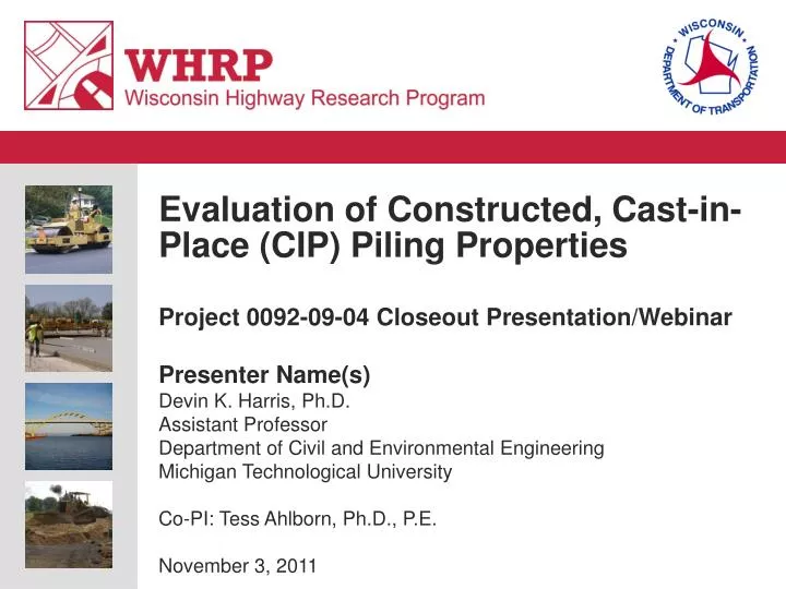
Evaluation of Constructed, Cast-in-Place (CIP) Piling Properties Project 0092-09-04 Closeout Presentation/Webinar Presenter Name(s) Devin K. Harris, Ph.D. Assistant Professor Department of Civil and Environmental Engineering Michigan Technological University

E N D
Evaluation of Constructed, Cast-in-Place (CIP) Piling Properties Project 0092-09-04Closeout Presentation/Webinar Presenter Name(s) Devin K. Harris, Ph.D. Assistant Professor Department of Civil and Environmental Engineering Michigan Technological University Co-PI: Tess Ahlborn, Ph.D., P.E. November 3, 2011
Presentation Outline • Project Overview and Objectives • Specimen Fabrication • Experimental Studies • Results • Conclusions/Findings • Questions and Discussion
Project Schedule and Budget • Project Awarded: November 11, 2009 • Draft Final Report Submitted: June 30, 2011 • 1 Project Extension (PI – due to injury) • 1 Administrative Extension (WHRP) • Award Amount: $90,000
Project Objective CIP tubular piles used by WisDOT in bridge and retaining wall structures • Characterize the axial capacity of typical (composite, non-composite, and core) • Investigate the level of composite action between the steel shell and concrete core • Assess the quality of the concrete core resulting from the placement method (free-fall)
Proposed Investigation • Phase I – Literature review • Phase II – Installation site survey • Phase III – Refinement of research plan • Phase IV – Pile fabrication • Phase V – Experimental testing program • Phase VI – Finite element analyses • Phase VII – Report/Presentation
Literature Review – Phase I • Existing literature yield limited result for CIP tubular piles • Results primarily related to bearing capacity • Literature primarily centered on tubular sections for buildings • Typically smaller with longer unbraced lengths • Review of current design methods (State Agencies, Design Codes, International) • Resistance vs. structural capacity based ✔
Pertinent Design Methods • Axial Compression (Squash Load) • Elastic/Inelastic buckling • Tables/Historical Practices
Design Methods • Resistance Based • Not investigated • Structural Capacity • Piling • AASHTO LRFD • Non-Composite • Composite
AASHTO Structural Capacity • Non-composite design
AASHTO Structural Capacity, cont. • Non-composite Design, cont. • 10 ¾ in. with 3/8 in. wall • 240 kip • 10 ¾ in. with ½ in. wall • 228 kip • 12 ¾ in. with 3/8 in. wall • 346 kip
AASHTO Structural Capacity, cont. • Composite Design
WisDOT Approach • WisDOT LRFD Bridge Design Manual • 11.3.1.12.2.1 – Driven Cast-in-Place Concrete Piles • Designed as reinforced concrete beam-columns, as described in LRFD [5.7.4.4 and 6.9.5.2] • For consistency with WisDOT design practice, the steel shell is ignored when computing the axial structural resistance
WisDOT Approach cont’d • WisDOT LRFD Bridge Design Manual • Current design • 75 tons (150k) on 10-3/4” (0.219” wall) • 105 tons (210k) on 12-3/4” (0.25” wall) • 125 tons (250k) on 14” (0.25” wall) *f’c limited to 3.5 ksi (Φ=0.75) with no long. reinforcement
AASHTO Structural Capacity* cont’d • Composite Design, cont. • 10 ¾ in. with 3/8 in. wall • 972 kip • 10 ¾ in. with ½ in. wall • 1170 kip • 12 ¾ in. with 3/8 in. wall • 1234 kip • Non-composite Design • 10 ¾ in. with 3/8 in. wall • 240 kip • 10 ¾ in. with ½ in. wall • 228 kip • 12 ¾ in. with 3/8 in. wall • 346 kip Note: Wall dimensions based on actual piles used in the study
Installation Site Survey – Phase II • Phase eliminated early on due to the challenge finding a participating contractor • WisDOT aligned the project team with a contract willing to assist (Pheifer Bros. Construction Co.) • Site selected based on existing project schedule (tasks were off the critical path)
Refinement of Research Plan – Phase III • Research plan finalized in collaboration with WHRP TOC Chair • Focus study on 10-3/4” and 12-3/4” diameter tubulars (at least 30 feet long) • Ensure piles selected satisfied WisDOT construction specifications (e.g. minimize welded sections)
Pile Fabrication – Phase IV • Piles driven in parallel with an ongoing new bridge construction site near Waupaca, WI. • 2 nominal pile sizes • 10-3/4” diameter • Wall thickness (0.375” and 0.5”) – seam welded • 12-3/4” diameter • Wall thickness (0.375”) – spiral welded • Appropriate pile diameters - thicker than expected* *Note: Contractors allowed to use increased wall thickness for ease of driveability
Pile Driving and Concrete Placement • On site installation • Driven ~15 ft. • Caissons for curing • Companion Cylinders cast • On-site concrete testing • 2-3/4” slump • 5% air content • 7-day concrete strength • 4,349 psi
Pile Removal and Transportation • Piles removed after 8 days of in place curing (6-4-10) • Transported to Michigan Tech Benedict Laboratory for Testing • Specimens stored outside (covered) for ~1 month (laboratory modifications and pile cutting coordination)
Pile Cutting and Preparation • Cutting performed by Cutting Edge Services Inc. • Diamond Wire Saw typical for subsea pipe cutting • 82 Cuts • 1-11ft. section • 2-12in. sections • 15 to 18-18in. sections • About 30 min a cut Hard Drive Video Weblink to Video
Final Pile Sections and Intended Use • 11 ft. Section • Future flexure testing on 10 ft. clear span • 12 in. Sections • Core samples • 18 in. Sections • Core Samples • Whole Section Loading • Core Loading • Push-through* * Determined post-cutting
Experimental Testing Program – Phase V • Compression Testing • Testing of the composite section (loading entire x-section) • Testing of core region (loading only core of entire x-section) • Testing of cored sections • Flexural testing • Push-through testing
Compression Testing • Objective – Evaluate the axial capacity of stub pile sections. The stub sections were deemed representative of the short unbraced lengths of embedded piles.
Experimental Set-ups (Compression) Coring internal specimens for cored compression testing Core centered plates Full section loading Core-only section loading
Compression Testing – Results (Whole section) 10-3/4” (1/2” wall) 12-3/4” (3/8” wall)
Compression Testing – Results (Core section) 10-3/4” (1/2” wall) 12-3/4” (3/8” wall)
Flexural Testing • Objective – Evaluate the composite action between the steel shell and concrete core. • Bond difficult to assess from an external perspective, but a change in linearity of strain distribution and slip would indicate loss of bond.
Flexural Testing - Results • Results did not provide a direct measure of bond strength, but demonstrated that the bond integrity is greater than the cracking strength of the composite section, as no slip was observed throughout the testing Strain vs. load (all gauges) for (10-3/4” – 0.375” wall) – Pile 1 Strain vs. load through cross-section depth (10-3/4” – 0.375” wall) – Pile 1
Push-through Testing • Objective – Evaluate the bond capacity in direct shear. Stub sections intended for compression testing were used for the push-through tests. Push-through loading
Experimental Set-ups (Push-through) Failure mechanism Test configuration
Push-through testing Seam welded Spiral welded
Push-through testing • Measured bond stress (0.29 – 0.53 ksi) • Literature: 0.2 – 2.0 ksi (concrete to rebar)
Finite Element Modeling – Phase VI • Specimen models • Compression specimens (Loading entire cross-section and Loading core only) • Embedded pile model • Variations in soil constraint conditions • Limited to validation range of experimental program • Models developed using ANSYS Commercial FEA software • Solid element models with full composite behavior
Finite Element Model – Specimen Comparison • L/D expected to yield fully plastic response rather than elastic buckling • Models limited to linear elastic region • Loading applied proportional to stiffness for uniform stress distribution (displacement-controlled) • Boundary conditions selected to ensure pure compression
Finite Element Model – Specimen Comparison 10-3/4” (1/2” wall) 12-3/4” (3/8” wall)
Finite Element Model – In-Service Behavior (Embedded in Soil) • End of pile assumed fixed due to bedrock • Contributions from vertical compaction, shear distortion, and lateral compaction • Soil response model as a series of discrete springs with equivalent stiffnesses • Loose sandy soil, compact sandy soil, loose gravel soil, and compact gravel soil • Loading limited to 1,000 kips based on testing
Finite Element Model – In-Service Behavior (Embedded in Soil) 10-3/4” (1/2” wall) 12-3/4” (3/8” wall) • Soil contribution matched stub section response
Findings and Recommendations • No compression failures were observed in the compression test specimens (no buckling, squashing) • True measure of axial capacity was not determined (limited to 1,000k frame capacity) • Specimens all exhibited capacities above 1,000 k (lower bound) > WisDOT design capacities (189-317%) • Non-linear response was observed in small specimens, but not failure • Previous studies indicated that typical failure mode should be squash failure
Findings and Recommendations • Loading mechanism has an influence on the behavior of the pile • Loading the entire x-section, as would be expected in-service yielded larger axial strain in the shell (more stiff than core-only loading scenario) • Loading only the core section of the x-section resulted in a delay in load sharing between the section components • Geometric non-linearities in cut sections resulted in inconsistencies between experimental and finite element model results • Finite element mode demonstrated that in-service conditions similar to stub section
Findings and Recommendations • All of the core concrete appear to be well consolidated and relatively uniform and free of voids • Assessment based on visual observation of cored specimens and cut ends of sections • Core compressive strength ranged from 6,000-9,400 psi vs. in-situ strength of companion cylinders of 7,600 psi. • Failure of some specimens during coring observed, but attributed to typical core extraction failure (based on successful removal of surrounding core samples). • Flexural testing results did not provide a direct measure of bond strength, but demonstrated that the bond integrity > cracking strength of the composite section
Findings and Recommendations • Current WisDOT practices is overly conservative with respect to the axial capacity • Uncertainty still remains with respect to long-term durability of steel shell (function of down-hole conditions ) • Bond is comparable to other steel/concrete composite systems • Core concrete is well consolidated using current placement methods.
Questions and Discussion Contact Information Devin K. Harris, Ph.D. Assistant Professor Department of Civil and Environmental Engineering Michigan Technological University dharris@mtu.edu Thank you for your attention