Download
1 / 19
190 likes | 372 Views
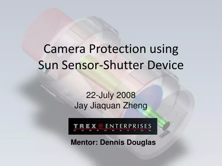
Camera Protection using Sun Sensor-Shutter Device. 22-July 2008 Jay Jiaquan Zheng. Mentor: Dennis Douglas. Overview of Sun Sensor – Shutter Device. Analogy: Human Eye & Camera Purpose Of Sun Sensor – Shutter Device Introduction of Sun Sensor – Shutter Device System Diagram

E N D
Camera Protection using Sun Sensor-Shutter Device 22-July 2008 Jay Jiaquan Zheng Mentor: Dennis Douglas
Overview of Sun Sensor – Shutter Device • Analogy: Human Eye & Camera • Purpose Of Sun Sensor – Shutter Device • Introduction of Sun Sensor – Shutter Device • System Diagram • Overall Preliminary Design • Detailed Design of System • Sun Sensor • Electrical Components • Solar Shutter • Summary & Path Forward • Has design met specification • Future goals
The Human Eye Provides A Conceptual Basis For A Solar Sun Sensor • Brain – Sun Sensor • Eyelid – Solar Shutter • Eye – Camera Sun Sensor Solar Shutter Camera ……There’s a reason they tell you not to look into the sun!
Preliminary Design Locates Sun Sensor & Shutter Device On A Telescope Shutter Sun Sensor front Telescope Housing back SS Design: Extend/Retractable Ray-Box, pinhole in front, optical detector in the back. Shutter Design: Slider-Crank using Rack & Pinion assembly driven by a Micromotor. • SS boresighted to telescope • Shutter mounted on back of telescope • Can be apply to ALL telescopes
Optical Power Input (sun light) Detector OPD OPM Convert to Electrical Power (voltage) ADC (Analog Digital Converter) Pinhole 1 Convert to Mechanical Power (Torque) Slider –Crank Mechanism Microprocessor 2 Lid Motor 3 Overall System Diagram Links Functionalities Of COTS And Custom Components COTS = Commercial Off The Shelf Components
SolidWorks Modeling Suggests Sun Sensor (Ray-Box) Design Meets Specifications Detector Housing Back Mount Pinhole Extender Thread pattern • Housing • Adjustable : Threshold: 10o – 60o • Determine by: Distance: Detector – Pinhole • Complete CAD Assembly Constructed in SolidWorks
Ray-Box Geometry Allows For Multiple Solar Exclusion Angles To Be Set pinhole Sun Position 1 detector θ Sun Position 2 Geometric Relationship: a b r R L R θ r L
Adjusting Length Of Sun Sensor Corresponds To Specific Solar Threshold Angle • Detector Radius, • R : 5.207 mm • Pinhole Radius, • r : 1.500 mm • Threshold Angle • -Given by Optical Straylight Analysis • Cameras can be damage • when reached
Detecting Threshold Angle Using Voltage Curve Generated By Optical Power Meter • Red area represents • Threshold Angle = Solar Exclusion Zone Optical Power Meter outputs voltage depends on incident light 30o summer detector 25 mm Voltage reading winter 0 OPM Sun Positions
Computing Unit Analysis Signal From Sun Sensor Effectively Controls Shutter Device • Analog to Digital Converter (ADC) • OPM outputs analog signals, Microprocessor could only read digital signals. • Microprocessor • Controls motion of motor in Shutter device
SolidWorks Modeling Of Shutter Provides Spatial Tolerances & Structural Properties Lid Motor Slider-Crank Rack & Pinion Ball Slide If it takes 10 seconds for your eyelid to close when looking directly at the Sun…
Rack & Pinion Assembly Slider-Crank Mechanism Designed using Dynamic Analysis. Ball Slide Motor • Synthesized based on Position, Velocity & Force/Stress Analysis. • Selected based • on Max Torque. Selected based on sliding distance. Superimposing All Major Components Allows For Analysis Of Effective Shutter Design
Position Analysis & Motion Of Slider-Crank Modeled Using Matlab Programming Lid slider
Velocity Analysis Of Slider-Crank Generates Relationship Between Lid And Slider Velocity o c A b B C fix O a Lid Velocity Polygon Slider Note: All terms defined in Position Analysis except slider velocity , or vs .
Dynamic Analysis Performed On Rack & Pinion System Based On Kinetic Energy Theory I R T x, vs m T – motor torque x – rack displacement R – gear radius I – gear inertia m – rack mass • Equivalence Inertia • Dynamics Model
Motor Linkage Factor Safety Maximum Allowable Pressure P n Lg T Gears R,I $ Customer Slider Acceleration (x,y,z) a Response Time Lid Velocity vl vs Slider Velocity d Slide Block Diagram Demonstrates Design Process And Components Specifications of Shutter Device Dimension Material Position Calculation Output Purchase Parts Designer Input Customer Specification
GUI Interface Allows User Input To Optimize Design Based On System Parameters and Variables
Summary and Path Forward Effective Sun Sensor-Shutter Device can be constructed using Commercial Off The Shelf and custom components. Modeling suggests this device will have a time response of 0.4 seconds and perform safely. Future goal is to determine costs of COTS and custom equipments and integration plan...
Acknowledgement Dennis Douglas, Daron Nishimoto, Riki Maeda, Chet Jonston Lani LeBron, Scott Seagroves, Lynne Raschke, Lisa Hunter The Akamai Internship Program is funded by the Center for Adaptive Optics through its National Science Foundation Science and Technology Center grant (#AST-987683) and by grants to the Akamai Workforce Initiative from the National Science Foundation and Air Force Office of Scientific Research (both administered by NSF, #AST-0710699) and from the University of Hawaii.