Download
1 / 26
260 likes | 414 Views
ANALYSIS OF TRANSMIT ANTENNA SELECTION/MAXIMAL-RATIO COMBINING IN RAYLEIGH FADING CHANNELS. IEEE TRANSACTIONS ON VEHICULAR TECHNOLOGY, VOL. 54, NO. 4, JULY 2005 Student : 96325508 CWChou Advisor : Dr.JT Wang. OUTLINE. Introduction System model Simulation Conclusion References. OUTLINE.

E N D
ANALYSIS OF TRANSMIT ANTENNASELECTION/MAXIMAL-RATIO COMBINING IN RAYLEIGHFADING CHANNELS IEEE TRANSACTIONS ON VEHICULAR TECHNOLOGY, VOL. 54, NO. 4, JULY 2005 Student : 96325508 CWChou Advisor : Dr.JT Wang
OUTLINE • Introduction • System model • Simulation • Conclusion • References
OUTLINE • Introduction • System model • Simulation • Conclusion • References
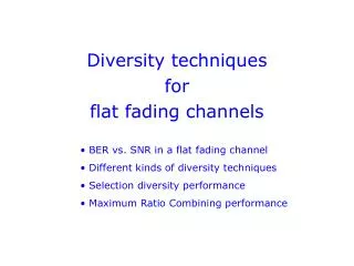
INTRODUCTION • In this paper, we investigate a multiple-input multiple-output (MIMO) scheme combining transmit antenna selection and receiver maximal-ratio combining (the TAS/MRC scheme). • SNR BER Transmit Antenna Number
OUTLINE • Introduction • System model • Simulation • Conclusion • References
SYSTEM MODEL • TAS • MRC • TAS/MRC • Flow chart • BPSK • STBC • Flat Rayleigh fading channel
SYSTEM MODEL • TAS • MRC • TAS/MRC • Flow chart • BPSK • STBC • Flat Rayleigh fading channel
SYSTEM MODEL • TAS • MRC • TAS/MRC • Flow chart
SYSTEM MODEL • TAS • MRC • TAS/MRC • Flow chart
SYSTEM MODEL • TAS • MRC • TAS/MRC • Flow chart
SYSTEM MODEL • TAS • MRC • TAS/MRC • Flow chart
OUTLINE • Introduction • System model • Simulation • Conclusion • References
OUTLINE • Introduction • System model • Simulation • Conclusion • References
CONCLUSION • TAS+MRC • Pilot bit BER • Capacity BER
OUTLINE • Introduction • System model • Simulation • Conclusion • References
REFERENCES • [1] S. M. Alamouti, “A simple transmit diversity technique for wireless communications,” IEEE J. Sel. Areas Commun., vol. 16, pp. 1451–1458,Oct. 1998. • [2] V. Tarokh, H. Jafarkhani, and A. R. Calderbank, “Space-time block codesrom orthogonal designs,” IEEE Trans. Inf. Theory, vol. 45, pp. 1456–1467, Jul. 1999. • [3] Z. Chen, B. Vucetic, J. Yuan, and K. L. Lo, “Space-time trellis codeswith two, three and four transmit antennas in quasi-static flat fading channels,”in Proc. IEEE ICC’02, New York, Apr. 2002, pp. 1589–1595. • [4] M. Z. Win and J. H. Winters, “Analysis of hybrid selection/maximal-ratio combining in Rayleigh fading,” IEEE Trans. Commun., vol. 47, pp. 1773–1776, Dec. 1999. • [5] S. Thoen, L. Van der Perre, B. Gyselinckx, andM. Engels, “Performanceanalysis of combined transmit-SC/receive-MRC,” IEEE Trans. Commun.,vol. 49, pp. 5–8, Jan. 2001.
Thanks for your attention….. Have a nice day!