Download

1 / 31
310 likes | 430 Views
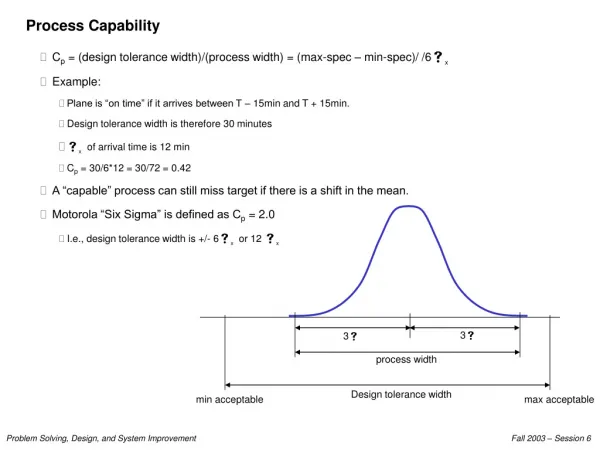
Ammonia Analyzer Provides Real Time Process Control Capability. PWO Operator Seminar – February 22, 2002 Greg Farmer - Littleton / Englewood WWTP Gary Girolimon - Ted Miller and Associates. Littleton / Englewood WWTP Process Schematic. Before Automating Process Control.

E N D
Ammonia Analyzer Provides Real Time Process Control Capability PWO Operator Seminar – February 22, 2002 Greg Farmer - Littleton / Englewood WWTP Gary Girolimon - Ted Miller and Associates
Before Automating Process Control Diurnal ammonia variations led to: • Breakpoint chlorination • Inconsistent fecal coliform counts
Benefits • Dial in Final Effluent Ammonia Concentration • Centrate Return Timing Feedback • Maximize Nitrifying Trickling Filter (NTF) Efficiency • More Consistent Fecal Coliform Counts Through Control of Ammonia to Chlorine Ratio • Only 2-3 hours/month Maintenance
NTF Effluent Ammonia Control Modes By-Pass Valve Control • 24 / 7 Effluent ammonia goal is 2.0 mg/l • Valve opens incrementally when ammonia is below 2.0 mg/l • Valve closes incrementally when ammonia above 2.0 mg/l Pump Control • If ammonia level increases above 7.0 mg/l, NTF pump speeds increase • When ammonia falls below 5.0 mg/l pump speeds decrease. • Pumps cannot go below a preset speed so that the minimum hydraulic loading is maintained.
By-Pass Valve Control If the analyzer detects ammonia level below the set point, the by-pass valve opens incrementally. If the analyzer detects ammonia levels above the set point, the by-pass valve closes incrementally.
By-Pass Valve Operation Ammonia > Nitrate> < Valve position Valve opens when ammonia level decreases below set point of 2 mg/l. Valve closes when ammonia level increases above set point of 2 mg/l.
Pump Speed Control If the analyzer detects ammonia levels above a set point the NTF pump speeds increase. If the analyzer detects ammonia levels below a set point the NTF pumps speeds decrease. Pump speed cannot go below a selected value so that the minimum hydraulic loading is maintained.
Pump Speed Control Operation Nitrate > < Ammonia < NTF Pump Output By-pass valve Position >
Instrument AccuracyAnalyzer vs. Lab Instrument values are extracted daily at 8:00 am and logged to the historical data server. Operators collect a sample near the analyzer at ~8:00 am for analysis by the lab.
Nitrate Buoy <---- Calibrated Properly -----> Recalibrated During Regular Maintenance - Suspect Poor Quality 3rd party Reagent
STIP Process Buoy • Operates by being placed directly in wastewater (even activated sludge) • Separate buoys for ammonium and nitrate
STIP Process Buoy • Follows EPA approved methods of analysis • Operates in a batch analysis mode with typical analysis times of 3 to 5 minutes • Measuring range of 0.1 - 50 mg/l as N for both nitrate and ammonium
Method of Analysis - General • Solenoid valve opens permitting sample to fill settling chamber via hydrostatic pressure • Sludge settles for pre programmed time period • Ammonium and nitrate measured with ion selective electrodes (ISE) • Solenoid valve reopens permitting supernatant to fill measurement chamber
Method of Analysis - NH4N • Caustic (NaOH) added till pH>11.5 • Ammonium is converted to Ammonia (gas) • Ammonia measurement taken with gas selective electrode
Method of Analysis - NO3N • Conductivity sensor used to add reagent (ion suppression) to adjust ionic strength of solution • Concentration measured with nitrate selective electrode
Calibration • Buoy calibration is done using three step standard addition method • Calibrated automatically once per day
Process Buoy In Open Position • Shows • Settling Chamber • Measuring Chamber • Electrodes • Valves • Amplifiers
Controller • One controller can operate two buoys • LCD screen displays current reading and graph of last 6-hours of operation • Outputs: • 4-20 mA • Bi-directional RS 232