Download
1 / 50
500 likes | 736 Views
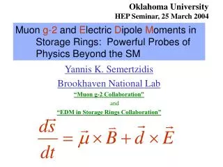
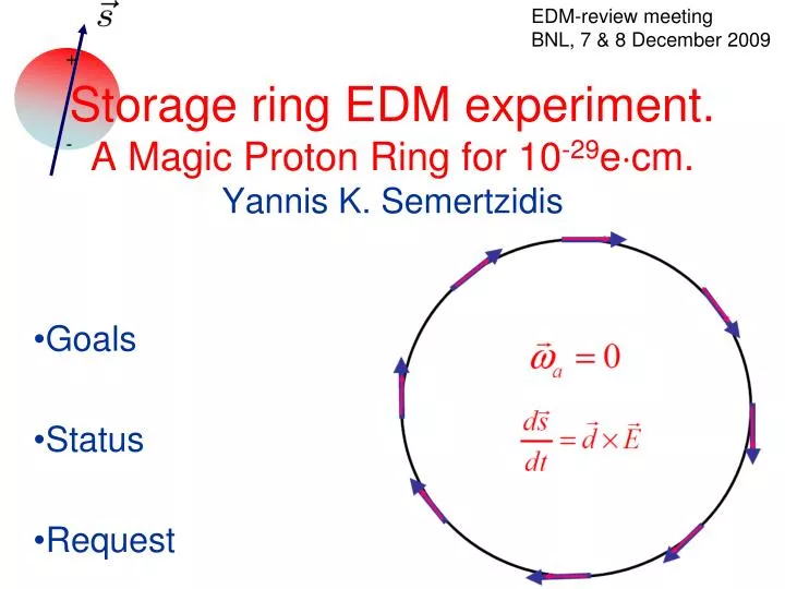
EDM-review meeting BNL, 7 & 8 December 2009. Storage ring EDM experiment. A Magic Proton Ring for 10 -29 e cm. Yannis K. Semertzidis. +. -. Goals Status Request. Well defined goals:.

E N D
EDM-review meeting BNL, 7 & 8 December 2009 Storage ring EDM experiment.A Magic Proton Ring for 10-29ecm.Yannis K. Semertzidis + - Goals Status Request
Well defined goals: Beam intensity with 2×10¹⁰ polarized protons per ~103s storage (P80%), (dp/p)rms=2.5×10-4, emitt. (95%, un-norm.): 3m hor. and 10 m ver. Long Spin Coherence Time (SCT) of ~103s, statistics, (R&D) Beam Position Monitors (BPM), 10nm, 1Hz BW, eliminates main systematics, (R&D) Internal Polarimeter to monitor the proton spin as a function of time, systematics < 1ppm, (R&D) E-field gradient of ~17MV/m for 2 cm plate separation, ~240 m ring circumference, (R&D)
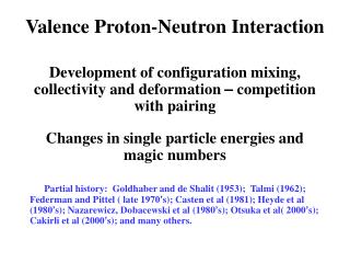
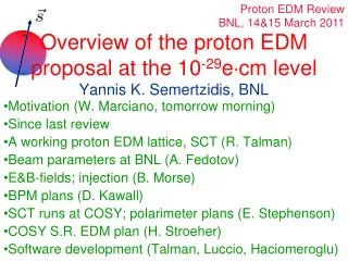
Physics reach of magic pEDM (Marciano) The proton EDM at 10-29e∙cm has a reach of >300TeV or, if new physics exists at the LHC scale, <10-7 rad CP-violating phase; an unprecedented sensitivity level. The deuteron EDM sensitivity is similar. • Sensitivity to new contact interaction: 3000 TeV • Sensitivity to SUSY-type new Physics:
+ - The Electric Dipole Moment precesses in an Electric field The EDM vector d is along the particle spin direction Yannis Semertzidis, BNL
A charged particle between Electric Field plates would be lost right away… + + -
…but can be kept in a storage ring for a long time Yannis Semertzidis, BNL
The sensitivity to EDM is optimum when the spin vector is kept aligned to the momentum vector Momentum vector Spin vector Yannis Semertzidis, BNL
Freezing the horizontal spin precession • The spin precession is zero at “magic” momentum (0.7 GeV/c for protons, 3.1GeV/c for muons,…)
A possible magic proton ring lattice: ~240m circumference with ES-separators. I.K.: Injection Kickers P: Polarimeters RF: RF-system S: Sextupoles Q: Quadrupoles BPMs: ~70 Beam Position Monitors
E-field plate module: The (26) FNAL Tevatron ES-separators would do 0.4 m 3 m Vertical plates are placed everywhere around the ring to minimize vertical electric fields from image charges
Magic Proton EDM ring includes: • Injection • Bunch capture with RF • Vertical to horizontal spin precession • Slow extraction onto an internal target for polarization monitoring • Use RF-feedback from polarimeter to keep spin longitudinal
pEDM polarimeter principle: probing the proton spin components as a function of storage time “defining aperture” polarimeter target extraction adding white noise to slowly increase the beam phase space carries EDM signal small increases slowly with time carries in-plane precession signal
Is the polarimeter analyzing power good at Pmagic? YES! Analyzing power can be further optimized (E. Stephenson)
Spin precession at rest E + Compare the Precession Frequencies with E-field Flipped: - Yannis Semertzidis, BNL
Main Systematic Error: particles have non-zero magnetic moments! For the nEDM experiments a co-magnetometer or SQUIDS are used to monitor the B-field For the magic proton ring we plan to use simultaneous clockwise (CW) & counter-clockwise (CCW) beam storage
Certain (main) systematic errors easier to handle if CW & CCW is done at the same time (Coincident BeamS: CBS) In a ring with Electric field bending it is possible to store protons CW & CCW at the same time in the same place
Two different focusing options for the magic proton ring • Magnetic focusing. The direct magnetic field effect is eliminated. Need to limit vertical forces other than magnetic. BPMs critical to eliminate the fields from the counter-rotating beams. • Electric focusing. Vertical forces other than magnetic are irrelevant. BPMs critical to eliminate low level radial B-fields. Systematic errors are very different in the above two focusing systems.
Proton EDM parameters during storage • Proton EDM with a statistical goal of 10-29 ecm within ~4×10⁷s. • Proton momentum 0.7 GeV/c, kinetic energy: 232MeV, beta~0.6. • Two simultaneously counter-rotating beams in one ring (same place). • 2x10¹⁰ particles per storage • The beam is bunched with h=120, f=90 MHz • We will have resonant cavities and/or striplines for position monitoring (BPMs).
CBS: All major previous field issues have been ~eliminated (intensity independent) and greatly reduced (intensity dependent) • At a price: Need BPMs with 10nm, 1 Hz BW relative resolution 1pm on average around the ring, over ~107s. • The good news: CBS can resolve the dynamic range and stability issues because the needed information is relative. • BPM Players so far: M. Blaskiewicz, P. Cameron, B. Morse. A BPM team is needed.
CBS: Main effects that don’t automatically cancel (remedy) • Self fields. Need: horizontal to vertical coupling per store < 10-4, and on average (107s) < 10-6. We plan to use beam-based alignment (BBA). • Fields from the counter-rotating beams (BPMs) • RF-cavity fields, if there is a substantial energy loss/turn (longitudinal impedance <1-10 K) • Polarimeter: proved <1ppm (mostly done-see talk by E. Stephenson)
R&D outline and Milestones for the proton EDM.Duration of R&D: up to 3 years
Goals and considerations E-field strength: 170kV/cm, 2cm plate distance Polarimeter systematic errors to 1ppm (early to late times-not absolute!). The EDM signal is ~3ppm early to late change in (L-R)/(L+R) counts. Spin Coherence Time (SCT): ~103s BPMs: 10 nm, 1Hz BW resolution
E-field strength (see talk by Morse) The field emission withoutand withhigh pressure water rinsing (HPR) for 0.5cm plate separation. Recent developments in achieving high E-field strengths with HPR treatment (from Cornell ILC R&D)
Polarimeter Systematic errors: off-axis/angle motion(See talk by Stephenson) Observable: L-R counting rate asymmetry as a function of time (expected signal level is ~3ppm). Possible syst. error sources: a) Target position changes from early (~1s) to late times (103s). b) The beam axis changes from early to late times c) …
Polarimeter team Polarimeter work • The Polarimeter team run at the COSY storage ring (Juelich/Germany) with stored polarized deuteron beams and compared signals from opposite (large) vertical polarizations. • The systematic error is extrapolated to be <1ppm for pEDM • Candidate detector technologies based on Multi Resistive Plate Chambers (MRPC) and Micro-Megas (MM) are under development in Frascati/Rome and Dimokritos/Athens respectively.
Simulations team Spin Coherence Time • Due to beam momentum spread dP/P there is spread in the horizontal spin precession. • The linear part of the spread is canceled by using RF-cavity. The quadratic part by using compensating sextupole magnets. • We expect to demonstrate (with simulation) ~103s by end of 2010 using realistic fields.
Cancelling the 2nd order effects with sextupoles • Strategically placed sextupoles around the ring will cancel the effect from dp/p, horizontal and vertical betatron oscillations. Method applied at Novosibirsk. Our case is analyzed by Y. Orlov who estimated SCT of 103s should be possible.
SCT Plan: two tracking programs for cross-checking • COSY-Infinity (developed expertise and need to support running the interesting cases). See talk by G. Onderwater (KVI) • UAL-based tracking program (in-house development). See talk by F. Lin (BNL) • Analytical estimations by Yuri Orlov (Cornell) • In addition: We need realistic tracking for a) magic proton ring lattice optimization, b) systematic error checking
Spin and Beam Dynamics teamSCT(1&2), Analytical Estimations, Systematic errors • Working Lattice • SCT • Systematic errors • Include fringe fields and position errors • Re-estimate SCT • Re-estimate Systematic errors • Lattice optimization • Simulate COSY-ring, observe SCT & compare w/ exp. • Simulate/optimize BPM-based feedback system, Beam Based Alignment, etc.
BPMs (a possible program) • Observe Signals at a collision point at RHIC using existing BPMs • Design resonant cavities • Build cavities & electronics • Test cavities in the lab • Test cavities at an accelerator • Test cavities at a collision point in an accelerator
Proton Statistical Error (230MeV): p : 103s Polarization Lifetime (Spin Coherence Time) A : 0.6 Left/right asymmetry observed by the polarimeter P : 0.8 Beam polarization Nc : 21010p/cycle Total number of stored particles per cycle TTot: 107s Total running time per year f : 0.5% Useful event rate fraction (efficiency for EDM) ER : 17 MV/m Radial electric field strength (65% azim. cov.)
Need support to develop (fully loaded costs) Total: ~$4M • SCT (statistics), improve the state of the art by ~102; COSY-INF.:$1M, UAL+SPINK: $0.5M • BPMs (systematics), eliminate the main systematic errors. Need ~10 nm, 1 Hz BW resolution; $0.45M + hardware • Polarimeter (statistics and systematics). Build and test a full scale polarimeter detector; $1M • E-field gradient: 17MV/m for 2 cm plate distance. Larger E-field smaller ring & higher sensitivity cheaper ring; $0.6M
Technically driven Milestones Spring 2008, Proposal to the BNL PAC 2010-2013 R&D phase; ring design Fall 2010: E vs. gap studies; simulation and design of polarimeter; 1st phase of SCT studies; design of BPM cavity Fall 2011: Polarimeter construction; SCT including placement errors & fringe fields; BPM cavity construction and electronics development, test in lab. Spring 2012: Finish first full scale E-field module test Fall 2012: Finish commissioning and calibration of polarimeter detector at COSY; Full scale tracking simulation package for EDM ring in place; Test cavity BPMs at a collision point using stored beams 11 14 07 08 09 10 12 13 15 16 17
What we have accomplished • Have developed the magic proton EDM ring concept. CBS: Simplest SR EDM experiment. It may be expandable to greatest sensitivity: p, d. • Developed expertise on COSY-Infinity: a high accuracy/efficiency spin tracking software to study the SCT and systematic errors and developing a second (in house) tracking program for comparison. • Polarimeter development runs at COSY/Germany are providing great results.
Possible Upgrade Modify EDM ring to do the deuteron EDM experiment with similar sensitivity (major upgrade) If a non-zero EDM value is found in one of them we will have a good idea of the CP-violation source (theta-QCD or new physics)
Why does the world need another EDM experiment? The proton,deuteron and neutron combined can pin-down the source should a non-zero EDM value is discovered. Critical: they can differentiate between a theta-QCD source and beyond the SM. The proton and deuteron provide a path to the next order of sensitivity. Yannis Semertzidis, BNL
Summary • The success of the proton EDM experiment hangs on our ability to develop BPMs with a relative position resolution better than 10 nm for 1 Hz BW, SCT of ~103s, highly efficient and low systematic errors Polarimeter detector,anda reliable E-field with E~17 MV/m for 2 cm plate separation. We believe those are all well defined, manageable goals. We need a very strong endorsement to move forward. • At 10-29 e-cm the proton EDM experiment will have the best sensitivity for beyond the SM CP-violation.
AGS Complex m g-2 experiment pEDM @ 17 MV/m pEDM Ring NSRL 30.8m Linac Booster AGS 100 m TTB C-AD Admin
pEDM Ring pEDM @ 17 MV/m 30.8m 100 m
Electric Dipole Moments: P and T-violating when // to spin T-violation (under CPT conservation) implies CP-violation, which is needed to explain why matter is dominating over anti-matter in our universe
CW and CCW injections in the magic proton ring Yannis Semertzidis, BNL
A possible solution for simultaneous CW and CCW beams (Yuri Orlov) Beta-Min Beta-Min Beta-Max Beta-Max
Motivation (Peter Cameron’s slide) • pEDM Coincident Beam Scheme (CBS) requires • one picometer measurement of relative positions of the two beams • with a bandwidth of one year • see BNL pEDM web site for further details • This can be accomplished with (obsolete, cumbersome, and expensive) COTS electronics (Libera Brilliance) • We want to get to 1pm in the first month, refine the experiment from there • In principle, and as the problem is presently understood, this can be accomplished • Development effort for pickups and electronics is underway • As a first step in exploring possible unknown systematics of the measurement we propose an APEX experiment
Prior work PRST , Accel & Beams, 11, 062801 (2008). Achieved res. ~8nm per ~10^10 electrons/bunch
From the September 2008 run at COSY Polarimeter team Resonance crossing using RF-solenoid (full spin flip) Vector asymmetry V+ T− Unp V− T+ Slowly extracting the beam while monitoring its polarization as a function of time
SCT team, F. Lin et al. Searching for optimum sextupoles (Preliminary res.) SCTS Two sets of sextupoles are next to focusing and defocusing quads. Both horizontal and vertical motions are included.
Technically driven pEDM Timeline Spring 2008, Proposal to the BNL PAC 2008-2012 R&D phase; ring design Fall 2009 Conceptual Technical Review at BNL Fall 2012, Finish R&D studies: a) Develop BPMs, 10 nm, 1 Hz BW resolution b) spin/beam dynamics related systematic errors. c) Polarimeter detector development and prepare for testing d) Finalize E-field strength to use e) Establish Spin Coherence Time, study systematic errors, optimize lattice FY 2013, start ring construction FY 2015, pEDM engineering run starts FY 2016, pEDM physics run starts 11 14 07 08 09 10 12 13 15 16 17
Technically driven pEDM Timeline June 2010 CD0 June 2011 CD1 Fall 2012 CD2 Fall 2014 CD3 Start of 2012, finish pEDM detailed ring design FY 2013, start ring construction FY 2015, pEDM engineering run starts FY 2016, pEDM physics run starts 11 14 07 08 09 10 12 13 15 16 17