Download
1 / 33
330 likes | 449 Views
Noise Model for Multiple Segmented Coupled RC Interconnects. Andrew B. Kahng, Sudhakar Muddu † , Niranjan A. Pol ‡ and Devendra Vidhani* UCSD CSE and ECE Department, abk@ucsd.edu † Sanera Systems, Inc., muddu@sanera.net ‡ Cadence Design Systems, npol@cadence.com

E N D
Noise Model for Multiple Segmented Coupled RC Interconnects Andrew B. Kahng, Sudhakar Muddu†, Niranjan A. Pol ‡ and Devendra Vidhani* UCSD CSE and ECE Department, abk@ucsd.edu †Sanera Systems, Inc., muddu@sanera.net ‡Cadence Design Systems, npol@cadence.com *Sun Microsystems, dv@eng.sun.com
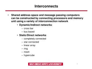
Outline of Talk • Signal Integrity Issues • Previous Works • Our Contributions • Transformed Model for Segmented Aggressors • Multiple Aggressors • Simulation Results • Conclusions
Outline of Talk • Signal Integrity Issues • Previous Works • Our Contributions • Transformed Model for Segmented Aggressors • Multiple Aggressors • Simulation Results • Conclusions
Factors Affecting Signal Integrity • Interconnect Induced Issues • scaled linewidths, increased aspect ratios, larger die sizes greater wire and via RC, electromigration, IR drop, skin effect • more metal layers higher coupling to ground ratio • long wider metal wires magnetic field / inductance • Process Induced Issues • low device thresholds, low VDD increased susceptibility to low noise margins • Design Induced Issues • high frequency faster slew times, inductive effects, ground bounce
Focus: Crosstalk Issues • Cross talk caused by coupling between neighboring signals • Victim Net: Net being affected by coupling • Aggressor Net: Net affecting victim net due to its coupling to victim • Coupling capacitance is one of major contributors • Functionality Issues • peak noise • false switching of noise sensitive nodes in the design • Timing Issues • positive/negative delay impact due to crosstalk • issues with timing closure • Motivation: find coupling related noise issues ASAP!! • In general, find signal integrity problem earlier in design • provide sufficient conditions for finding problem
Outline of Talk • Signal Integrity Issues • Previous Works • Our Contributions • Transformed Model for Segmented Aggressors • Multiple Aggressors • Simulation Results • Conclusions
Previous Works on Crosstalk • Vittal et. al., 97: L model; step input; ignore Rint, Cint • Kawaguchi et. al., 98: diffusion equations; step input; same peak noise expressions as Vittal • Nakagawa et. al., 98: L model; assumptions about peak noise time • Shepard et. al., 97: L model; ignores R and C of aggressors; uses ramp with heuristics; does full chip simulation • Kahng et. al., 99: model; Assume single, full length aggressor
Previous Works on Crosstalk • Circuit models issues • use lumped capacitance models • cannot handle segmented aggressors configurations • Noise models issues • estimations very pessimistic • assumptions about R and C • some are simulation based
Outline of Talk • Signal Integrity Issues • Previous Works • Our Contributions • Transformed Model for Segmented Aggressors • Multiple Aggressors • Simulation Results • Conclusions
Improved circuit model for peak noise facilitates segmented aggressors superposition for multiple aggressors Methodology for coupled RC interconnects only takes drivers into account considers slew times considers lumped -Model considers both local and global line Our Work
Two parallel coupled lines Aggressor - Green; Victim - Red Coupling capacitance - Cc Supply voltages - Vs1, Vs2 Circuit Model Driver 1 Load 1 Aggressor Line Vs1 Cc Load 2 Driver 2 Victim Line Vs2
Rd1, Rd2: Driver Resistances Cgv1, Cgv2: Leg of model for ground cap for victim Cga1, Cga2: Leg of model for ground cap for aggressor Aggressor Line Vs1 CL1 Ra Rd1 B A Cc2 Cc1 Rv Rd2 C D Cgv2 CL2 Cgv1 Vs2 Victim Line Lumped - Model Cga2 Cga1 Ra, Rv: Wire resistances of used in the model Cc1, Cc2: Left and right leg of model for coupling cap CL1, CL2: Load caps
Peak Noise For Model • Vpeak is given at vc(tpeak) where
Simple lumped model deficiencies for general case general case is when aggressor and victim nets are not overlapped completely for segmented aggressor overlaps, lumped model gives pessimistic results Extensions to lumped model for general case improved victim wire and victim driver resistance modeling improved victim coupling and ground capacitance modeling For multiple segmented aggressor nets coupling to victim net, use superposition to compute noise peak value Segmented Aggressor Nets
Segmented Aggressor Net Configuration • L1 = Left fraction of Victim to the Aggressor Overlap • L2 = Fraction of Victim overlapped by Aggressor • L3 = Right fraction of Victim to the Aggressor Overlap • RdA(RdV) = Aggressor(Victim) Driver Resistance • RwA(RwV) = Aggressor(Victim) Wire Resistance • CgA(CgV) = Aggressor(Victim) Capacitance to ground • CLA(CLV) = Aggressor(Victim) Load Capacitance • Cc = Coupling Capacitance VA RdA CgA CLA Aggressor Net RWA CC RdA L2 L3 L1 RWV Victim Net CgV RdV CLV L1+ L2+ L3 = 1
Victim wire resistance modeling Wire resistance to left and right of overlap region not considered part of wire resistance in the model Assumed proportional to length of the victim net overlap region with the aggressor, I.e., Rv = Rwv* L2 Victim driver resistance modeling Assumed to consist of the actual driver resistance and the resistance of portion of wire to the left of the overlap region, I.e., Rd2 = Rdv+Rwv* L1 Victim Resistance Modeling
Coupling capacitance distribution in model and real circuit In real circuit, coupling capacitance starts L1 distance away from the keeper end of the victim net In the model, the left leg of the coupling capacitance is at the keeper end of the victim net Discrepancy between model and real circuit In real circuit, capacitance is shielded by the wire resistance In the model, the keeper end of the victim net is at zero potential This causes more discharge from the left leg of coupling cap Solution Lower the coupling cap on the keeper end of the victim net in the model Keep it pessimistic (don’t worry about receiver end correction) Cc1= 0.5 * Cc* (1-L1) Cc2= 0.5 * Cc* (1+L1) Non Uniform Coupling Capacitance Distribution
Ground capacitance distribution / discrepancy In real circuit, the ground capacitance is distributed all along the victim wire In the model, the ground capacitance is visible equally at driver and receiver end of the wire Solution Make left (right) leg of ground cap account for the ground cap for the portion of the victim wire to the left (right) of the overlap region Adjust total ground capacitance such that the total ground capacitance is not changed Cgv1 = 0.5* Cgv * (1+L1-L3) Cgv2 = 0.5* Cgv * (1-L1+L3) Non Uniform Victim Ground Cap Distribution
Outline of Talk • Signal Integrity Issues • Previous Works • Our Contributions • Transformed Model for Segmented Aggressors • Multiple Aggressors • Simulation Results • Conclusions
In real life layouts, need to see contributions of not more than 3 worst aggressors Our model report noise by superposition for individual aggressor’s noise contribution Noise function due to each aggressor is added in time domain to obtain the superimposed peak noise Could potentially be huge number of aggressor configurations Presented results for two and three aggressors Multiple Aggressors
Outline of Talk • Signal Integrity Issues • Previous Works • Our Contributions • Transformed Model for Segmented Aggressors • Multiple Aggressors • Simulation Results • Conclusions
Simulation Configuration Criteria • global wires (case 2 and 3) and local wires (case 1 and 4) • different coupling to ground capacitance ratios • The values shown here are corresponding to Rint, Cint per unit length of the victim wire and coupling cap to the aggressor with L2 assumed equals 1.0 • To compare results for model with spice, we construct multiple model with 45 nodes in the spice circuit
Segmented Aggressor Net Configuration 1 • L1 = Left fraction of Victim to the Aggressor Overlap = 0.2 • L2 = Fraction of Victim overlapped by Aggressor = 0.6 • L3 = Right fraction of Victim to the Aggressor Overlap = 0.2 • RdA(RdV) = Aggressor(Victim) Driver Resistance • RwA(RwV) = Aggressor(Victim) Wire Resistance • CgA(CgV) = Aggressor(Victim) Capacitance to ground • CLA(CLV) = Aggressor(Victim) Load Capacitance • Cc = Coupling Capacitance VA RdA CgA CLA Aggressor Net RWA CC RdA L2 L3 L1 RWV Victim Net CgV RdV CLV L1+ L2+ L3 = 1
Peak Noise Results for Configuration 1 Peak noise results for configuration 1: L1=0.2, L2=0.6, L3=0.2
Segmented Aggressor Net Configuration 2 • L1 = Left fraction of Victim to the Aggressor Overlap = 0.0 • L2 = Fraction of Victim overlapped by Aggressor = 0.6 • L3 = Right fraction of Victim to the Aggressor Overlap = 0.4 • RdA(RdV) = Aggressor(Victim) Driver Resistance • RdA(RdV) = Aggressor(Victim) Wire Resistance • CgA(CgV) = Aggressor(Victim) Capacitance to ground • CgA(CgV) = Aggressor(Victim) Load Capacitance • Cc = Coupling Capacitance Aggressor Net VA RdA CgA CLA RWA CC L2 L3 RWV Victim Net RdV Cgv CLA L1+ L2+ L3 = L
Peak Noise Results for Configuration 2 Peak noise results for configuration 1: L1=0, L2=0.6, L3=0.4
Segmented Aggressor Net Configuration 3 • L1 = Left fraction of Victim to the Aggressor Overlap = 0.4 • L2 = Fraction of Victim overlapped by Aggressor = 0.6 • L3 = Right fraction of Victim to the Aggressor Overlap = 0.0 • RdA(RdV) = Aggressor(Victim) Driver Resistance • RdA(RdV) = Aggressor(Victim) Wire Resistance • CgA(CgV) = Aggressor(Victim) Capacitance to ground • CgA(CgV) = Aggressor(Victim) Load Capacitance • Cc = Coupling Capacitance Aggressor Net VA RdA CgA CLA RWA CC L1 L2 RWV Victim Net RdV Cgv CLV L1+ L2+ L3 = L
Peak Noise Results for Configuration 3 Peak noise results for configuration 1: L1=0.4, L2=0.6, L3=0
Peak Noise Results for Two Aggressor Peak noise results for two aggressors configurations. Aggressor1: L1=0, L2=0.6, L3=0.4; Aggressor2: L1=0.4, L2=0.6, L3=0
Peak Noise Results for Three Aggressors Peak noise results for three aggressors configurations. Aggressor1: L1=0, L2=0.6, L3=0.4; Aggressor2: L1=0.2, L2=0.6, L3=0.2; Aggressor3: L1=0.6, L2=0.4, L3=0
Outline of Talk • Signal Integrity Issues • Previous Works • Our Contributions • Transformed Model for Segmented Aggressors • Multiple Aggressors • Simulation Results • Conclusions
Conclusions • Model works for point to point victim net and segmented multiple aggressors • Results are accurate for peak noise • Pessimism increases with the number of aggressors • One segmented aggressor: 16% max error • Two segmented aggressor: 17% • Three segmented aggressor: 31% • Can be used as a quick pruning step in an analytical noise tool
Future Work • More scalable for large system of aggressors • Extension to tree like structures (multiple fanouts) • Report pulse width / slew degradation and effective switch factor • Form a complete analytical system for post layout noise analysis