Download
1 / 36
360 likes | 484 Views
Noise and Delay Uncertainty Studies for Coupled RC Interconnects. Andrew B. Kahng, Sudhakar Muddu † and Devendra Vidhani ‡ UCLA Computer Science Department, abk@cs.ucla.edu † Silicon Graphics Inc., muddu@mti.sgi.com ‡ Sun Microsystems, dv@eng.sun.com. Outline of Talk.

E N D
Noise and Delay Uncertainty Studies for Coupled RC Interconnects Andrew B. Kahng, Sudhakar Muddu† and Devendra Vidhani‡ UCLA Computer Science Department, abk@cs.ucla.edu †Silicon Graphics Inc., muddu@mti.sgi.com ‡Sun Microsystems, dv@eng.sun.com
Outline of Talk • Signal Integrity issues • Previous works • Our Contributions • Circuits Models • Delay and Noise Equations • Simulation results • Conclusions
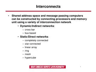
Factors Affecting Signal Integrity • Interconnect induced issues • scaled linewidths greater wire and via RC • increased aspect ratios greater wire and via RC • larger die sizes greater wire and via RC • more metal layers higher coupling to ground ratio • Process Induced Issues • low device thresholds increased susceptibility to low noise margins • low VDD increased susceptibility to low noise margins • high frequency faster slew times
Focus: Crosstalk Issues • Functionality Issues • peak noise • false switching of noise sensitive nodes in the design • Timing Issues • delay uncertainty • maximum difference between maximum and minimum victim line delay over all possible cases of switching activity on neighboring aggressor line(s) • Motivation: find noise issues ASAP!! • find signal integrity problem earlier in deisgn • provide sufficient conditions for finding problem
Outline of Talk • Signal Integrity issues • Previous works • Our Contributions • Circuits Models • Delay and Noise Equations • Simulation results • Conclusions
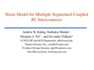
Previous Work on Signal Integrity • Vittal et. Al., 97: L model; step input; ignore Rint, Cint • Kawaguchi et. Al., 98: diffusion equations; step input; same peak noise expressions as Vittal • Nakagawa et. Al., 98: L model; assumptions about peak noise time • Shepard et. Al., 97: L model; ignores R and C of aggressors; uses ramp with heuristics
Previous Work on Signal Integrity Issues • Circuit models issues • use lumped capacitance models • use charge sharing models • Noise models issues • estimations very pessimistic • assumptions about R and C • assume zero slew rate • some are simulation based
Outline of Talk • Signal Integrity issues • Previous works • Our Contributions • Circuits Models • Delay and Noise Equations • Simulation results • Conclusions
Improved peak noise and delay and noise models better peak noise estimates analytical equations for delay uncertainty Methodology for coupled RC interconnects only takes drivers into account considers slew times considers both lumped L-Model and -Model considers both local and global lines Our Work
Circuit model L model model Noise analysis and peak noise expressions Delay analysis and delay uncertainty Our Work
Two parallel coupled lines Aggressor - Green; Victim - Red Coupling capacitance - Cc Supply voltages - Vs1, Vs2 Circuit Model Driver 1 Load 1 Aggressor Line Vs1 Cc Load 2 Driver 2 Victim Line Vs2
Charge Sharing Model • No resistance • Lumped capacitance - C1, C2 • Load capacitance - CL1, CL2 • Node C has noise voltage Aggressor Line Vs1 CL1 C1 B Cc1 C C’1 CL2 Vs2 Victim Line
Noise Analysis For Charge Sharing Model • Basic noise analysis model • Victim line quiet • Aggressor line switching • Peak noise defined by ratio of coupling capacitance to total capacitance of wire
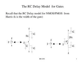
Lumped L Model • All resistances considered • Lumped capacitances • Different slew times considered Aggressor Line Vs1 CL1 C1 R1 Rd1 B Cc1 R’1 Rd2 C C’1 CL2 Vs2 Victim Line • Solve using nodal equations at B and C
Solving L Model • M1,M2,a1,and a2,are given as • Transfer functions for nodes B and C are
Noise Analysis For L Model • L model voltage function for ramp input at victim node C (TS is slew time) • L model peak noise expression for step input reduces to Vittal et. Al. peak noise expression
Peak Noise For L Model • Differentiate vc(t) to get tpeak • L Model peak noise at tpeak
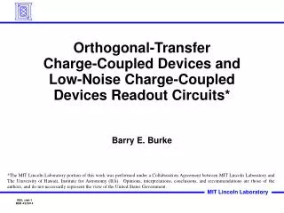
Aggressor Line Vs1 CL1 C2 C1 R1 Rd1 B A Cc2 Cc1 R’1 Rd2 C D C’2 CL2 C’1 Vs2 Victim Line Lumped - Model
Peak Noise For Model • Vpeak is given at vc(tpeak) where
Delay Uncertainty • Maximum difference between maximum and minimum delay • Caused by crosstalk between victim and aggressor switching simultaneously • Maximum delay by worst case • Aggressor and victim switching in opposite directions • Minimum delay by best case • Aggressor and victim switching in same direction
Vs1 V0 0 V0 Vs2 0 Ts2 Ts1 Simultaneous Switching of Victim & Aggressor • General Case • both victim ramp (TS2) and aggressor ramp (TS2) and four regimes of operation • Our Case: first region is empty Time
Delay Uncertainty • Our delay uncertainty study based on Model • Corresponding voltage function at node C
Delay Function • Delay Function at node C
Outline of Talk • Signal Integrity issues • Previous works • Our Contributions • Circuits Models • Delay and Noise Equations • Simulation results • Conclusions
Simulation Results • Simulation configuration • 0.25 micron technology • analyzing different metal layer wires • analyze different factors like slew, coupling cap, etc. • Peak noise results w.r.t. slew • Best and worst delay result • Delay uncertainty w.r.t. aggressor slew and coupling
Simulation Configuration • Criteria • global wires (case 2 and 3) and local wires (case 1 and 4) • different coupling to ground capacitance ratios
Peak Noise Results • Peak noise for different models • Comparison with previous work (Vittal et. Al. and Kawaguchi et. Al.) • Our results considered different slew times at aggressor
Peak Noise Results • Peak noise for different models • Comparison with previous work (VittalM97 and Kawaguchi-Sakurai) • Our results considered different slew times at aggressor
Peak Noise Variation For Local Wires • Peak noise variation with respect to slew of aggressor for local wire case 1
Peak Noise Variation For Global Wires • Peak noise variation with respect to slew of aggressor for global wire case 3
Victim Delay Results (Best/Worst Case) • Worst case delay values using 50% threshold delay • Aggressor and victim switching in opposite directions • Same slew time on victim and aggressor • Case 1 and 4 - local • Case 2 and 3 - global
Victim Delay Uncertainty With Slew Times • Delay uncertainty constant with same slew time on victim and aggressor • accuracy within 15% of spice
Victim Delay Variation W.R.T. Coupling • Best and worst case delays variation with coupling capacitance variation • Same slew time on victim and aggressor • Case 1 is local interconnect and case 2 is global interconnect
Victim Delay Variation With Aggressor Slew • Impact of aggressor slew on delay • Victim slew constant at 400 ps • 15% accuracy w.r.t. spice • Local interconnect (case1) delay highly sensitive to slew time
Victim Delay Variation With Aggressor Slew • Impact of aggressor slew on delay • Victim slew constant at 400 ps • 15% accuracy w.r.t. spice • Local interconnect (case1) delay highly sensitive to slew time
Conclusions • Provide simple, fast and accurate analytical expressions for peak noise and delay estimates • Consider all R and C and all slew times • Provide noise awareness methodology possibility earlier in design phase • Easy extensions • multiple aggressor lines • slew offsets