Download
1 / 56
560 likes | 697 Views
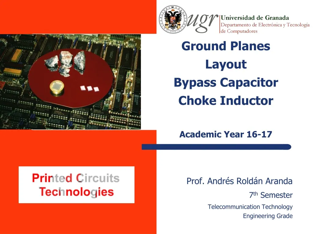
Ground Planes Layout Bypass Capacitor Choke Inductor Academic Year 1 6 -17. Prof. Andrés Roldán Aranda 7 th Semester Telecommunication Technology Engineering Grade. Contents. 1.- General layouts desing strategy 1.1.- Source of problems EMI Parasitics elements

E N D
Ground PlanesLayoutBypass CapacitorChoke InductorAcademic Year 16-17 Prof. Andrés Roldán Aranda 7th Semester Telecommunication Technology Engineering Grade
Contents 1.- General layouts desing strategy 1.1.- Source of problems • EMI • Parasitics elements 1.2.- Layout techniques • Track layout. Mass connections. • Mass plane. • Bypass’ Capacitor • Shock inductors • Shielding
Electromagnetic Interference Electromagnetics interference (EMI): It is the process by which the electromagnetics waves are transmitted from an electronic system to another one by conducted or radiated paths.
Parasitic Elements Parasitics elements • The paths and ways aren’t ideal conductors. They have parasitic resistance and inductance. • Between conductors or closer paths will generate unwanted parasitics capacities and inductances. Unwanted effects from parasitics elements • Coupling through common impedance • Capacitive coupling. • Inductive coupling. • Rebouncing • Modification of characteristics of filters and oscillators
Slew Rate This parameter is the easiest way to track the effects of the electromagnetics coupling between close paths. The SR defines the maximum variation of the output voltage, but also defines the slope of the voltage line.
Slew Rate http://www.amplifier.cd/Tutorial/Slew_Rate/SlewRate.htm
How to relation EM with SR? Ampère’s Law If we have 2 conductive lines, close enough to be affected by the magnetic field from the other line, the variation of current in one line, will change the magnetic flux that it’s been directed to the other line. Then, the other line, is going to create an opposite current to recover the natural state , and then, if we relation with the Ohm’s law, we will have a current with a resistance from the conductive line, which means a variation of voltage. This variation in an amount of time is the SR
Ampère’s LawFaraday’s Law Mawell’s Equiations
Common Impedance Coupling The referenced voltage of circuits A and B is modified by currents IA and IB Pass of signals between circuits
Coupling Effects - Rparasitic Coupling by common impedance. Example 1: Operational amplifier Ideal case Real case IRload 15 cm path of 35 um thickness and 4 mm widthfor current returnwhich has a 0.015 ohm resistance Av = - 400 Vin2 = 10 mV (100KHz) Rload = 50 ohm Vout2 = 4 V
Coupling Effects - Rparasitic Coupling by common impedance Example 1: Operational amplifier Vout2 = 4.55 V VRparasita = 1.36 mV IRload Vout2 = 4.55 V Iload = 4.55 V/50 ohm = 91 mA VRparasita = 0.015ohm x 91 mA = 1.36 mV ΔVout2 = 0.55 (= 1.36 mV x 400)
Coupling Effects – (L+R)parasitic Coupling by common impedance Example 1: Operational amplifier Do we miss something? IRload Lparasita = 145 nH
Capacitive Coupling • Voltage changes in one part of the circuit cause undesirable variations in another part of the circuit. • Capacitive coupling depends on: • length of both parallel lines • distance • The effect decreases proportionally to the frequency and R, and inversely proportionally to C (see ground planes)
Capacitive Coupling • Noise voltage at point 2 which is caused by fluctuations in point 1, it would be: • If we assume that: • and:
Capacitive Coupling • We want the noise voltage to be as low as possible. What we can do is to decrease the capacitor coupling C_12. • .Decreasing the area between layers • Increasing distance between circuits • Putting a shield between the circuits, but this has to be done carefully. • When putting a shield new capacitive coupling appear.
Capacitive Coupling • .SOLUTION: ground the shield • Finally the fluctuations on 1 don’t arrive at 2
Inductive Coupling • Coupling between the currents of different conductors • Greater influence when there are high currents with an abrupt transient and low impedance circuits. • The coupling coefficient (Lgr) depends on: • areas formed by emitter and receiver conductors • distance between both circuits • relative orientation (parallel distance between circuits) • Lower effect if: low frequencies, high resistance, current return ground run
Inductive Coupling – Ground Bouncing Self-intuctance efects. Example 1: ground bouncing including parasitic impedance Bouncing in Vout + - + - • Solution: -Wide paths, or (planos) - Bypass capacitors
Inductive Coupling – Frequency offset Effects of self-inductance. Example 2: oscillator Fosc = 27 MHz
Inductive Coupling – Frequency offset Effects of self-inductance. Example 2: oscillator Connection wires Lstray inductance = 1 µH Fosc = 12.5 MHz
Contents 1.- General layouts designs strategies 1.1.- Problems sources • EMI (Electromagnetic Interference) • Parasiticselements 1.2.- Layout technique • Ground plan • Track layout. Ground connection • Bypass capacitor • Shock inductors (ferrite beads) • Shielding
Ground Plane Ground plane Mass can be carried to the different PCB circuits by three structures: • Minimum • The tracks lead the mass to the circuits • Possible high inductance between point of mass • Not recommendable • Grid • Ground plane
Ground Plane Impedance Ground plane • Conductor structure of lowest possible impedance that serves as a return current and voltage reference Thickness Cu: 0.035 mm Trackwith 1 mm of widthand 10 mm long
Ground Plane Impedance Mass´s map More advantages: • Low parasite impedance. • “Rebounds” problem is reduced. • EMIs shielding. • Capacitive coupling is reduced. • Parasite inductance is reduced.
Ground Plane Impedance Mass´s maps.Recommendations. Maximize mass´s map. masa • Colocar numerosas vías conectando planos de masa • Colocar vías a planos de masa cerca pines de masa de ICs Evitar metalizaciones flotantes.
Ground Plane Impedance Track layout. Ground connections • Identify the tracks which contains the most sensitive signal • Avoid loops (they favor to the inductive coupling and act like antenna) and reduce the area • Reduce parallel length between circuits and layout from the same or different layer (it favors to the capacitive and inductive coupling)
Ground Plane Impedance • If we don’t consider the necessity of a security ground point, the ground connection system can be configured of three different ways: • Only point (low frequency) • Multipoint (High frequency) • Hybrid (Low and High frequency) Only point Multipoint Hybrid
Connection scenarios One pointMultipointHybrid • Used when f > 1 Mhz and in digital circuits. • Using short connexions to the ground is advised as well as employing ground planes. • Low impedance thanks to the ground planes (low inductance) • Not adapted for low frequencies. • Used only when f < 1MHz • The conductor’s inductance can raise its impedance. • In low frequencies, ensure low resistance (Increasing equivalent strains must be avoided in circuits placed far from the ground) • Provides different connexions to the ground for high and low frequency signals.
Connection scenarios Only point Multipoint • This is the most simple. It eliminates the coupling for impedance and the ground loop in low frequency • Use only if f < 1 MHz • The inductance of the conductors can raise its impedance • With low frequency, ensure low resistance (avoid reference tension increase in circuits remote to the ground) • The most noisy circuits should be place near to the common point • Use for f > 1 MHz and digital circuit • Try to use short ground connections. Use grounds planes. • Low impedance due to the ground plane (It’s low inductance) • Not to use for low frequency
Connection scenarios • It uses reactive components (condensers and inductances) • The connections ground system should works different in low frequency an RF. • Care must be taken that parasitic resonances are not introduced in the reactive components. Hybrid
Bypass Capacitor Bypass capacitors • Used to establish a low-impedance path to ground for non-desired high frequency signals. • Recommended to stabilize voltage at supply pins, voltages references, ... • For example, reduce ground bounces
Bypass Capacitor applicaton Self-induction effects. Examplen°2 : oscillator Fosc = 27 MHz Cbypass = 100 nF
Bypass Capacitor vs. Frequency Bypass capacitors Problema: Parasitic elements. Resonance and inductive behaviour.
Bypass Capacitor application Self-inductance effects. Example 1: Power source • A bypass capacitor shorts AC signals to ground, soAC noise that may be on a DC signal is removed, and a clean, pure DC signal goes through without any AC ripple. For example, important when using a power source. We desire: • We get:
Bypass Capacitor application Self-inductance effects. Example 1: Power source • AC noise is quite common when using a DC power supply connected to an AC power outlet. Normally, at 50/60 Hz as that is the most usual frequency for AC. • The value of the bypass capacitor is normally set as 1/10 th of RE at the lowest frequency intended to be bypassed.
Bypass Capacitor application Self-inductance effects. Example 2: oscillator Fosc = 27 MHz Cbypass = 100 nF
Bypass Capacitor vs. Frequency Condensadores de bypass Problema: elementos parásitos. Resonancia y comportamiento inductivo
Usage of Bypass Capacitors Soluciones: • Ubicar los condensadores tan próximos al IC como sea posible (minimización de la inductancia parásita) • Situar en paralelo con un condensador de elevada capacidad otro de capacidad menor (y con resonancia a frecuencia más alta). También para capacidades de desacoplo
Usage of Bypass Capacitors Solutions • Locate the capacitors as close to the IC possible (minimization of the parasite inductance) • Place in parallel with a capacitor of high capacity another one of smaller capacity (and with higher frequency resonance).Also for decoupling capabilities.
Usage of Bypass Capacitors Soluciones: • Conseguir valores de capacidad empleando capacidades menores colocadas en paralelo
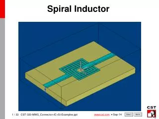
Usage of Choke Inductors Choke inductor • They are used in high frequency (usually in Radio Frequency) circuits to avoid these signals moving between circuits or part of them. • They are often set between the power supply and the components pins or in tracks betwwen two circuits It avoid RF signals to pass to the power supply.(and from the power supply to other circuits) Special attention to the bypass capacitor 3.2 mm (L) x 1.6mm (W) x 0.9mm (D) Low frecuancy lines. Chokes avoid the pass of RF signals and its radiation to other tracks in the circuit.
Usage of Choke Inductors For a fixed value of L, if frequency increase, impedance increases, so high frequency signals will be blocked by the choke • Zchoke=2pi*f*L • Typical choke inductors used in PCB
Usage of Choke Inductors RF Amplifier schematic In this schematic, RFC are chokes. They keep RF signals in RF circuits (like the input and output impedance matching circuits or the transistor) and avoid RF signal to arrive to the DC source.
Electromagnetic shielding Shielding • Barrier for transmitting electric and magnetic fields Reduce the risk of inductive and capacitive coupling • Minimize reception and emission of electromacnetic waves Reduce EMIs • Ground planes act as electromagnetic shields • Some times it is necessary add some extra EM shields • All EM shields must be interconnected. Each shield must have, at least, 2 low impedance conectors to ground.
Electromagnetic shielding This shield protects all ICs from Electromagnetic interferences (It is a Faraday Cage) Example of shielding in a mobile phone. See how Shields are conected with ground Translated by:Pablo Jesús García Martínez
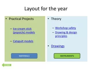
Agenda 2.- Diseño de PCBs con señales mixtas AD 2.1.- Fuentes de problemas 2.2.- Técnicas de layout • Distribución de componentes • Trazado de pistas • Masa
Component Placing Distribución de componentes Dispositivos de alta frecuencia (> 40 MHz) próximos a los conectores o fuentes de alimentación Separación de partes analógica y digital
Bypass Capacitor Component Placing Distribución de componentes Condensadores de bypass Condensador de 10 ó 100 μF cerca de la alimentación Por cada CI (analógico o digital) un condensador de desacoplo (tan próximo como sea posible al CI). Valor: 1 μF (f < 1 MHz) 0.1 μF (f > 10 MHz)
Signal straps layout • De nuevo, separación de pistas con señales analógicas y digitales • Para minimizar acoplamientos capacitivos entre pistas dos estrategias: Modificar dimensiones y distancia entre pistas Insertar una pista conectada a masa • Pistas con señales tan cortas como sea posible (para evitar capturar señales no deseadas) • Prestar atención especialmente a las entradas de dispositivos analógicos (suelen tener altas impedancias de entrada y, por tanto, son más sensibles a la inyección de corrientes parásitas)
AD mixed signal PCB Grounding: • If possible, ground planes shall be used • If not, the star ground solution shall be applied, with the track as wide as possible Master Tip: Don’t let the return current from the digital electronic go through the analog ICs