Download

1 / 19
200 likes | 529 Views
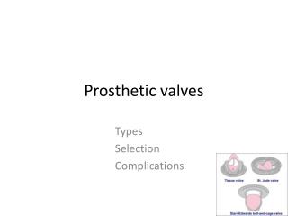
DESIGN OF WIRELESS PROSTHETIC HAND . Amardeep Bajwa Thapar University (Patiala), Punjab. Contents. Introduction Why Wireless robotic arm System Description Block Diagram System Operation Conclusion References

E N D
DESIGN OF WIRELESS PROSTHETIC HAND Amardeep Bajwa Thapar University (Patiala), Punjab
Contents • Introduction • Why Wireless robotic arm • System Description • Block Diagram • System Operation • Conclusion • References • Photographs
Introduction • Prosthetic arms which are available in the market are classified as • Mechanical Arm • Electrical driven arm • Myo-electric arm • Mechanical arm operates using body power with the use of Bowden • cables. That cable is attached to the soldier with a string. When • the movement of the soldier occurs, the cable is stretched hence • opening & closing of plum takes place. • Electrically driven arm operates using relays & switches, no harness • cable is required. • With the advent of new technology arm prosthesis reached to a new • dimension results a new prosthetic arm , where the features of grip • force has been implemented & the whole system operates using EMG • signal (Signal from muscle)
Why Wireless Robotic arm • It has been seen that the signal strength from amputee stump decreases as the • years of amputation increases. • It is because the muscle slowly lost its elasticity, if it is unused for a number of • years • For the amputation above 20 years, the muscles permanently lost its • elasticity and comes under a permanent fatigue state. • EMG signal lost forever in that situation. So our state-of-the-art technology • (Myo Electric arm) will be of no use. • In this situation it is indeed a very challengeable task for rehabilitation. • Amputee needs all types of features like Myo electric arm but the feed signal • should not be EMG. • As a solution of the above stated problem, we have developed one wireless • robotic arm, in CSIO where all the features are present but the input feed is not • an EMG signal, It operates using wireless switch.
Block Diagram of RF Transmitter Figure 1. Block diagram of RF transmitter
Contd.. • Switches • All the switches are of Micro switch type • They are connected with four input data pins of Encoder • The switches are marked as “STOP”; “OPEN”; “CLOSE • WITH LOW GRIP”; “CLOSE WITH HIGH GRIP” (Right to • left) • Encoder • The encoder has 8 bit address bus, four bit data bus • One Transmission enable port pin, denotes whether the • transmission is successful or not • The address bus is grounded as no another device • except switches are connected • One internal crystal which provides the clock for data • transmission
Contd.. • RF Transmission module • This module is used for data modulation & transmission • The modulation type is AM • Carrier frequency is 434 MHz • Antenna for RF communication • It is a simple wire • It is stripped at another end, which acts as a simple wire • radiator antenna
Block Diagram of RF Receiver Figure 2. Block diagram of RF receiver with grip controlled circuitry
Contd.. • Antenna for RF Receiver • It is same as described in Transmitter section • RF Receiving module • This module is used for data demodulation & re shaping • The Demodulation type is AM • Carrier frequency is 434 MHz • Decoder • The decoder is synchronized with encoders in all prospect • The decoder has same 8 bit address bus, four bit data output. • All the data output pins are connected to the microcontroller • pins • One Valid Transmission port pin, denotes whether the • transmission is valid or not • The address bus is grounded • One internal crystal which provides the clock for data receiving
Contd.. • Microcontroller With Motor Driver • It is the heart of the whole system • All Four output pins from decoder and the Motor driver pins’ • are connected with microcontroller as shown in the block • diagram of receiver • The two limit switches measures the maximum extent of • opening & closing of Plum • The Opto Switches are used as a Limit Switch • Microcontroller drives the DC motor through Driver circuitry • as the signal (Low to High ) received from the Decoder output • pins. • External Pulse shaping circuit is used to control the duty cycle • of the pulses generates to control the speed of DC motor • The software written based on speed control of DC motor
Contd.. • Video of wireless prosthetic hand
Conclusion • The arm has been developed & Tested with 2 different level of grip • forces in CSIO • The wrist is not automatic, it is manually controlled Rachett based. • Level of the grip forces can be increased if the number of the • switches are increased in transmitter section. • Wrist rotation can be controlled electronically if the mechanical • arrangement can be modified and attached with motor shaft.
Photograph Figure: Transmitter & Receiver along with Hand
References [1] Ferguson, G Reg Dunlop, “Grasp Recognition from Myo electric Signal”, Proc. Australasian Conference on Robotics and Automation, 27-29, Nov 2002, Auckland [2] Andres Herrera, Andres Bernal, David Isaza and Malek Adjouadi, “Design of a Electrical Prosthetic Gripper using EMG and Linear Motion Approach”, the National Science Foundation grants EIA- 9906600 and HRD-0317692 [3] EdwinIversen, Harold H. Sears, and Stephen C. Jacobsen, “APPLICATIONS OF CONTROL”, IEEE Control Systems Magazine, pp 16-20, 2005 (doi: 10.1109/MCS.2005.1388792)