Download
1 / 45
450 likes | 618 Views
CLEMSON U N I V E R S I T Y. Dynamic Workcell for Industrial Robots. Dept. of Electrical and Computer Engineering Clemson University, SC. Yanfei Liu. Outline. Motivation for this research Current status of vision in industrial workcells

E N D
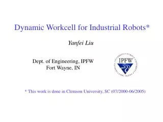
CLEMSON U N I V E R S I T Y Dynamic Workcell for Industrial Robots Dept. of Electrical and Computer Engineering Clemson University, SC Yanfei Liu
Outline • Motivation for this research • Current status of vision in industrial workcells • A novel industrial workcell with continuous visual guidance • Work that has been done • Our prototype: camera network based industrial workcell • A new generic timing model for vision-based robotic systems • Dynamic intercept and manipulation of objects under semi-structured motion • Grasping research using a novel flexible pneumatic end-effector
Motivation for this research • Current industrial workcells • No vision or a single snapshot in certain locations • Disadvantages • Cannot deal with flexible parts • Cannot deal with uncertainty
Motivation for this research • Our novel dynamic workcell design • Manipulation is integrated with visual sensing • Applications ( reduce fixtures, handle objects on the ship)
System architecture • A set of cameras embedded into the workcell • An industrial manipulator with its conventional controller
Experimental platform • Our prototype • Staubli RX130 manipulator with its conventional controller • Six cameras, wired to two PC-RGB framegrabbers mounted in a Compaq Proliant 8500 computer • V+ Operating systems and language • Alter command to accomplish real time motion
First part: A new generic timing model for vision-based robotic system
desired position e + power amplifiers control robot - camera Introduction • Classical visual servoing structure • eye-in-hand systems • Corke (1996), an eye-in-hand manipulator to fixate on a thrown ping-pong ball • Gangloff (2002), a 6-DOF manipulator to follow unknown but structured 3-D profiles. • part-in-hand systems • Stanvnitzky (2000), align a metal part with another fixed part • mobile robot systems • Kim (2000), a mobile robot system to play soccer
desired position e joint controller camera control robot encoders + - Introduction • Vision guided control structure • Allen (1993), a PUMA-560 tracking and grasping a moving model train which moved around a circular railway. • Nakai (1998), a robot system to play volleyball with human beings. • Miyazaki (2002), a robot accomplished a ping pong task based on virtual targets
Introduction • Three common problems in visual systems • Maximum possible rate for complex visual sensing and processing is much slower than the minimum required rate for mechanical control. • Complex visual processing introduces a significant lag (processing lag) between when reality is sensed and when the result from processing a measurement of the object state is available. • A lag (motion lag) is produced when the mechanical system takes time to complete the desired motion.
Previous work • the first two of the three problems have been addressed to some extent in previous works. All of these works neglect the motion time (motion lag) of the robot. • Corke and Kim, presented timing diagram to describe time delay, used discrete time models to model the systems and simplified these asynchronous systems to single-rate systems.
s2 s1 sensing u2 u1 image processing k q synchronizing tracking c1 … cN controlling finishing motion f processing lag motion lag Timing Model: notation
Timing Model: our prototype • Inherent values (obtained by analysis/measurement) • s = 33ms u = 19+30+14 = 63ms • wm = 39ms wf = (5+16+27)/3 = 16ms w = 39+16 = 55ms • l = s + u + w =151ms f = 130ms • User-variable values • c = 4ms q = 40ms
Experiments • Problem description • The most recently measured position and velocity of the object is where the object was (l+k) ms before, xt-l- k, vt-l- k • The current position, xt • N, d?
Experiments • Solutions Constraint:
Experiments: model validation • Setup • A small cylindrical object is dragged by a string tied to a belt moving at a constant velocity. • The robot will lunge and cover the object on the table with a modified end-effector, a small plastic bowl.
Experiments • Experiment description • We set q to two different values, 40 and 80, in these two sets of experiments. We let the object move at three different velocities. For each velocity, we ran the experiment ten times. • Results
Second part: Dynamic Intercept and Manipulation of Objects under Semi-Structured Motion
Scooping balls: problem description robot xt , yt : object position at time t vx , vy: object velocity at time t xr , yr: initial robot position xf , yf : final impact position x Unknown variables: yf , i y Closed loop Open loop Start tracking Make prediction (t) Impact (t+i)
Scooping balls: solution • Solutions • Object unsensed time • Time between the last instant when reality is sensed and the final impact time • Delay between visual sensing and manipulation
… … c1 c1 cN cN Timeline description: object unsensed time t processing lag(l) + k synchronizing tracking q q … controlling m 20 motion lag (f) finishing motion closed loop open loop t = l + k + 4m+ f m < N = 10, k < 30 + 14 = 44ms t = 151 + ( 40 + 44 ) / 2 +115 = 308ms
20 alters 10 alters impact point 10 alters 20 alters impact point Impact point z y
Equations • Solutions • Implementation • Predict the maximum acceleration of the object motion that the robot still can achieve a successful catch • Calculate the size of the end-effector in order to overcome the maximum acceleration of the moving objects
Experimental Validation • Setup • Two types of end-effector (bowl, two scoopers with different width). • Three types of interference (wind, bump, ramp) • Results • With wind interference
Experimental Validation • with bump interference, weighted corner • with bump interference, balanced
Experimental Validation • with ramp interference, weighted corner • with ramp interference, balanced
Third part: A Novel Pneumatic Three-finger Robot Hand
Related work • Three different types of robot hands • Electric motor powered hands, for example: • A. Ramos et. al. Goldfinger • C. Lovchik et. al. The robonaut hand • J. Butterfa et. al. DLR-Hand • Barrett hand • Pneumatically driven hands: • S. Jacobsen et. al. UTAH/M.I.T. hand • Hydraulically driven hands: • D. Schmidt et. al. Hydraulically actuated finger • Vision-based robot hand research • A. Morales et. al. presented a vision-based strategy for computing three-finger grasp on unknown planar objects • A. Hauck et. al. Determine 3D grasps on unknown, non-polyhedral objects using a parallel jaw gripper
Novel pneumatic hand • Disadvantages of current robot hands • Most robot hands are heavy • Even with visual guidance, the robot hand can only grasp stationary objects • Novel hand architecture • build-in pneumatic line in Staubli RX130 • Paper tube, music steel wire embedded inside • Camera mount adjusting “finger” spread angle • 120 degrees between each other
Novel pneumatic hand • Close position Open position • Our research here is to demonstrate that we use a novel idea to built a flexible end effector and it can grasp semi-randomly moving objects. This is not a new type of complex research tool-type robot hands.
ball track robot y x initial hand position final hand position Grasping research • Problem statement
Grasping research • Position prediction • Same as the method in the second part work of this research • Orientation adjustment • Line fitting to get the final “roll” angle • equations
Conclusions: timing model • A generic timing model for a robotic system using visual sensing, where the camera provides the desired position to the robot controller. • We demonstrate how to obtain the values of the parameters in the model, using our camera network workcell as an example. • Implementation to let our industrial manipulator intercept a moving object. • Experimental results indicate that our model is highly effective, and generalizable.
Conclusions: dynamic manipulation • Based on the timing model, we present a novel generic and simple theory to quantify the dynamic intercept ability of vision based robotic systems. • We validate the theory by designing 15 sets of experiments (1050 runs), using two different end effectors under three different interference. • The experimental results demonstrate that our theory is effective.
Conclusions: novel pneumatic hand • A novel pneumatic three-finger hand is designed and demonstrated. • It is simple, light and effective. • Experimental results demonstrate that this novel pneumatic hand can grasp semi-randomly moving objects. • Advantages • The compliance from pneumatics will allow the three-finger hand to manipulate more delicate and fragile objects. • In the experiments of grasping moving objects, unlike the traditional gripper, the contact position for this continuous finger is not very critical, which leaves more room for sensing error.
Sponsors • The South Carolina Commission on Higher Education • The Staubli Corporation • The U.S. Office of Naval Research
ramp interference bump interference The distribution of |vi – vavg | in the balance ramp and bump cases.
Determining the Values • An external camera to observe operation • A conveyor moving in a fixed path at a constant velocity • A light bulb as a tracking object • A laser mounted in the end effector of the robot