Download

1 / 14
140 likes | 237 Views
Convolution Reverb (a.k.a Project V-IR-BULL). Dain Marvel, Taylor Morris and Colt Hartstein Advisors: Dr. Wiley & Dr. Sankar http://usfconvolutionreverb.weebly.com/. Complete Design Review (CDR) January 27, 2013 EEL 4914 Senior Design Project. Problem Statement.

E N D
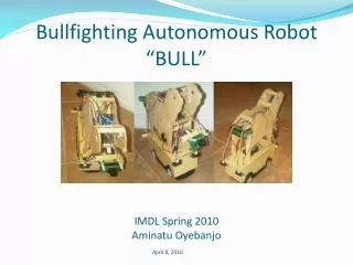
Convolution Reverb(a.k.a Project V-IR-BULL) Dain Marvel, Taylor Morris and Colt Hartstein Advisors: Dr. Wiley & Dr. Sankar http://usfconvolutionreverb.weebly.com/ Complete Design Review (CDR) January 27, 2013 EEL 4914 Senior Design Project
Problem Statement • In audio processing, reverberation is a commonly applied effectwhen recording tracks or when playing recorded songs. When sound is played back in a specific space, be it an amphitheater or a bathroom, the audio radiating from the initial source is reflected and bounced back and forth across the surrounding walls, floors and ceilings. This continues until the sound waves lose enough energy to be inaudible to the human ear. In our brains, thereverberant characteristicsof the space helps us to define the physical parametersof the room in which we are listening to this sound source. This is because the reverberation lends us auditory clues as to the characteristics of the room, such as the distance between walls and floor to ceiling, and the composition of the material used to construct them. • EX1: Very reflective materials sustain the propagation of the originating sound, as they do not absorb very much of the pressure waves' energy. • EX2: Larger spaces, like a concert hall or theater, will produce a much longer reverb effect, as the sound waves have longer distances to travel between reflections, thus elongating the time between absorption events • In both professional and consumer audio electronics, artificial recreations of acoustically desirable spaces are highly sought after in music playback. There are many existing methods by which this effect may be generated, but a lesser known concept in this endeavor is the use of convolution to attain these artificial characteristics. The more realistically the effect can recreate a space in our perception, the 'better' the reverb unit is considered. Our team is developing a system that will express these characteristics in playback by convolving a music source with the impulse response of a desired room or space;convolution reverb.
Design Approach • Our system, as will be seen in more detail in subsequent slides, will have three main stages: • IR capture • Convolution • Playback • This system we are developing will ultimately havetwo prototypes by the end of the design; one that appeals to the professional audio industry (recording studios,audio engineers, producers) and another more affordable version that will appeal to the consumer audio market (stereo systems and music playback devices used by the average listener). • The professional system will utilize audio capture and playback deceives that are optimized for near-perfect sound reproduction and recording, of which price tags tend to run up and outside the budget of an out-of-pocket consumer. • The consumer device will utilize more affordable audio equipment in capture and playback, at the expense of accuracy in near-flat band frequency response. This reduction in accuracy is an acceptable trade off in the consumer prototype, as the average untrained music listener does not readily perceive the majority of theinconsistencies in the less-expensive devices. • These changes in frequency response are glaringly obvious to the professional community. • Furthermore, the consumer community will only use this device to listen to completed songs and albums, like they use all other audio devices they purchase, whereas the professional community will use this in the recording process which creates the 'complete' music consumed.
Design of Components and Sub-Systems JTAG HEADERS RCA VIDEO OUT AUDIO OUT STATUS LEDS GPIO PINS 1.8V REG. USB 2.0 2.8V REG. DISPLAY DSI SD CARD SLOT 512MB RAM CPU & GPU CAMERA CSI POWER (5V 1A) 3.3V REG. ETHERNET OUT HDMI OUT
Design of Components and Sub-Systems Signal Flow • A chirp track is played out of a music player and sent into the mixer. • The mixer directs that signal to a preamplifier. • Pre-amplified signal sent to a point-source PA-monitor. • The PA plays the chirp in a specified space. • The microphone captures the chirp and the reverberated copies and reflections of the chirp from the room, thus giving the frequency and timing information necessary to generate an IR characteristic of the room. • The recorded audio signal will be sent from the mic through the preamp and into the Raspberry Pi for FFT analysis to produce an IR map for convolution. • A music track is sent to the convolution program and is convolved with the IR map. This affected signal is then sent from the processor in the Pi to the correct channel to output the processed signal through preamps and out finally to the headphones and/or pa for playback. • To be determined: number of channels necessary for headphones, a channel for the dry track, a channel for the chirp and a channel for the mic.
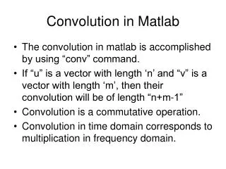
Simulation/Calculations • Simulation of a guitar track (pre-processing) convolved with a Plate Impulse Response (assumed to have been created from an excitation source of a starter pistol) done through MATLAB. • Results shown that silence inserted before the beginning of the impulse created a delay of x amount of seconds when convolved with the same guitar track. • Convolved files are nearly identical for stereo files so only one channel needed for convolution (mono). • “Chirp” file estimated to be under <25µs in duration.
* = Code: Visual Representation: Hardware/Software To Date Performing Convolution in MATLAB:
Initial calculation and basic convolution function implemented through MATLAB. Individual convolution through C++ language has yet to be coded and run (utilizes RackAFX software). Digital audio editing of sources and IR’s for simulation purposes done by Audacity 1.3. Hardware/Software To Date Performing Convolution in MATLAB:
Hardware/Software To Date Raspberry Pi: DPA4011 Microphone Mackie 1202VLZ Mixer Electro-Voice ZLX-12P Powered Monitors; 1000 Watts
Testing Plan • Debugging of the code (C++/Python/MATLAB) needed to find and troubleshoot any possible errors that can occur during operation. • Testing convolution reverb unit with multiple source types of varying frequency response and length of playback (vocal, guitar, drum set, piano, shaker, etc.) • The necessary level of the preamps in mixer to avoid distortion due to overdrive and to read i/o signal with optimum SNR: • sent to the PA, • coming out of the DPA4011 • sending a music track to the pi for convolving, • playback of the convinced signal into the playback headphones. • The most flat-band pick up pattern of the DPA4011
Action items • Obtain impulse responses of local locations on campus. • Consult Dr. Morgera for developing an envelope detector to eliminate low signals before the “chirp”. • Compile and run C++ audio convolution program code (debug as necessary). • Determine premiere method of convolution time domain vs. FFT method (comparison of delays). • Design and etch hardware circuits for portability, efficiency and functionality.
Summary Already Completed: • Impulse response capture researched (chirp vs. sine sweep). • Tested current reverb products (Lexicon 224 & 480, Bricasti 7 and PCM 60). • Gained permission for access to USF School of Music Concert Hall for IR capture. • Researched options and obtained audio hardware for capture and playback stages. • Signal flow for audio paths established • Researched language for programming Raspberry Pi • R&D on basic control functions of I/O ports on Pi What’s Next: • Complete IR capture of two vastly different acoustic spaces #presets • Test for optimal distance between speaker and microphone Ultimate Goals: • 100% control Raspberry Pi and all functions on wireless server • Portable battery-powered system • Design has two prototypes in development- for professional and consumer communities, • Three subsystems/3 Stages: • IR capture • Chirp, record, pre-amp in mixer, input to Pi • Convolution • FFT of recording- C/D convert, convolution algorithm run with dry track, • D/C back-convert, export to mixer • Playback of track+reverb