Download
1 / 15
150 likes | 264 Views
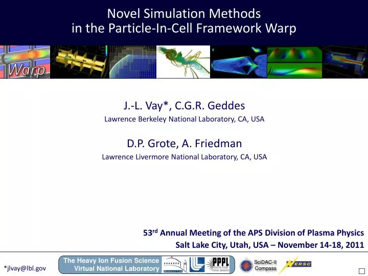
Novel Simulation Methods in the Particle-In-Cell Framework Warp. J.-L . Vay*, C.G.R. Geddes Lawrence Berkeley National Laboratory, CA, USA D.P. Grote , A . Friedman Lawrence Livermore National Laboratory, CA, USA. 53 rd Annual Meeting of the APS Division of Plasma Physics

E N D
Novel Simulation Methods in the Particle-In-Cell Framework Warp J.-L. Vay*, C.G.R. Geddes Lawrence Berkeley National Laboratory, CA, USA D.P. Grote, A. Friedman Lawrence Livermore National Laboratory, CA, USA 53rd Annual Meeting of the APS Division of Plasma Physics Salt Lake City, Utah, USA – November 14-18, 2011 The Heavy Ion Fusion Science Virtual National Laboratory SciDAC-II Compass *jlvay@lbl.gov
Warp is a versatile parallel 3D Particle-In-Cell framework developed by the Heavy Ion Fusion Science Virtual National Laboratory Standard PIC Laboratory frame Moving window Lorentz Boosted frame Examples: Beam generation Neutralization in plasma Example: Beam transport Example: Laser plasma acceleration Non-standard PIC Steady flow Quasi-static Example: Fast injector design Example: electron cloud studies 2-D slab of electrons p+ bunches Markers s e- clouds SPS - CERN 3-D beam
Modeling of 10 GeV laser plasma accelerator stage is challenging Calculation in boosted frame at ≈wake minimizes scale differences1 Lab frame Boosted frame g= gwake llaser << lwake << Laccelerate llaser ≈ lwake≈Laccelerate Predicted speedup: >10,000 for 10 GeV stage; > 1,000,000 for 1 TeV stage. 1 Vay, PRL 2007 But short wavelength instability observed at front of plasma for large g (≥100) Longitudinal electric field laser plasma Warp 2D simulation 10 GeVLPA (ne=1017cc, =130) Conjectured that instability related to numerical dispersion, i.e. a kind of numerical Cerenkov.
* An electromagnetic solver based on Non-Standard Finite-Difference (NSFD) was implemented in Warp NSFD: weighted average of quantities transverse to FD (). NSFD=FD if =0 Cole1and Karkkainen2have applied NSFD to source free Maxwell equations g -g b -b b FD -b g -g a -a g NSFD -g b -b b -b g -g Dx Warp3: switched FD/NSFD to B/E. => FD on source terms, i.e. standard exact current deposition schemes still valid. NSFD offers tunability of numerical dispersion Yee Cole-Karkkainen (CK) isotropic perfect dispersion 2D diagonal NSFD FD FD x=y=z) x=y=z) NSFD Yee/CK allows for perfect dispersion along3D/principal axes. 1J. B. Cole, IEEE Trans. Microw. Theory Tech.45 (1997), J. B. Cole, IEEE Trans. Antennas Prop.50 (2002). 2M. Karkkainen et al., Proc. ICAP, Chamonix, France (2006). 3J.-L. Vay, et al., J. Comput. Phys.230 (2011) 5908.
Perfectly Matched Layer1,2(PML) implemented with NSFD solver - for absorption of outgoing waves - NSFD NSFD FD FD Example: Reflection of circular pulse using 5 cells PML with quadratic progression and standard coefficients or improved coefficients2 1JP Berenger, J. Comput. Phys. 127 (1996) 363 2J.-L. Vay, J. Comput. Phys. 183 (2002) 367 Same high efficiency as with Yee.
After testing: instability mostly insensitive to numerical dispersion… …but very sensitive to time step! Sharp decrease of instability level at ct=z/√2 Power spectrum (a.u.) • Tunable NSFD solver allows ct=z/√2 time step for (near) cubic cells • ct=z/√2 time step restricted to “pancake” cells in 3D using Yee FDTD solver • Use of special time step was helpful but not sufficient for large g boost
1/4 1/2 1/4 Bilinear filter Digital filtering of current density and/or fields -- commonly used for improving stability and accuracy Multiple pass of bilinear filter + compensation routinely used 100% absorption at Nyquist freq. Bilinear (B) Bilinear (B) + compensation (C) Wideband filtering difficult in parallel (footprint limited by size of local domains) or expensive Example: wideband filters using N repetitions of bilinear filter 1×B + C 4×B + C 20×B + C 50×B + C 80×B + C
1/4 1/2 1/4 Bilinear filter with stride 2 “Strided” bilinear filters enable efficient and versatile filtering1 Using a stride N shifts the 100% absorption frequency to Fnyquist/N 4×BC stride 1 (G1) 4×BC stride 2 (G2) 4×BC stride 3 (G3) 4×BC stride 4 (G4) • Combination of filters with strides allows for more efficient filtering: • G1G2 20*B+C; speedup ×2 • G1G2G3 50*B+C; speedup ×3.5 • G1G2G4 80*B+C; speedup ×5.5 G1 × G2 G1 × G2 × G3 G1 × G2 × G4 20×B+C 50×B+C 80×B+C Nice, but is wideband filtering possible without altering the physics? 1J.-L. Vay, et al., J. Comput. Phys.230 (2011) 5908.
Laser field Time Hyperbolic rotation from Lorentz Transformation converts laser… …spatial oscillations into time beating Lab frame Laser field Time Wake frame
Spectrum very different in boosted and lab frames Time history of laser spectrum (relative to laser l0 in vacuum) Dephasing time Lab frame Frame of wake (=130) spectrum spectrum 0 0 Content concentrated around l0 Content concentrated at much larger l More filtering possible without altering physics*. *J.-L. Vay, et al., PoPLett. 18 (2011).
Controlling the numerical instability with tunable EM solver & filtering + new laser/particle injection and diagnostics through planes1: led to over 1 million x speedup2 Laser injection Particle injection Diagnostics 2J.-L. Vay, et al., PoPLett. 18 (2011) & PoP (in press). 1J.-L. Vay, et al., J. Comput. Phys.230 (2011).
Warp contains a lot more not described here, see • A. Friedman, D. P. Grote, and I. Haber, Phys. Fluids B4, 2203 (1992) – code description, warped coordinates • J.-L. Vay et al., Phys. Plasmas11 (2004) – mesh refinement • D.P. Grote et al., AIP Conf. Proc. 749, 55 (2005) – updated Warp description • R. Cohen et. al., Phys. Plasmas12, 056708 (2005) – “Drift-Lorentz” particle pusher • J.-L. Vay, Phys. Plasmas15, 056701 (2008) – ultra-relativistic pusher • R. Cohen et al. Nucl. Instr. & Methods 608, 53 (2009) – direct implicit Drift-Lorentz • For questions on Warp, email to • DPGrote@lbl.gov • Afriedman@lbl.gov • JLVay@lbl.gov
as well as Friedman damping algorithm - for noise control - B push modified to with where is damping parameter. Yee-Friedman (YF) Cole-Karkkainen-Friedman (CKF) Dispersion degrades with higher values of Damping more potent on axis and more isotropic for CKF than YF.
~10 GeV e- beam BELLA Project: state-of-the-art PWfacility for laser accelerator science BELLA Laser Gowning Room Control Room Plasma Final focus < 100 cm Laser