Download
1 / 13
130 likes | 277 Views
“A board for LKr trigger interface and proto-L0TP”. G.Lamanna (CERN) NA62 Collaboration Meeting in Brussels LKr-WG 7.9.2010. Introduction. The 2011 “alpha” run will be a good opportunity to test several detectors and the TDAQ systems

E N D
“A boardforLKr trigger interface and proto-L0TP” G.Lamanna (CERN) NA62 Collaboration Meeting in Brussels LKr-WG 7.9.2010
Introduction The 2011 “alpha” run will be a good opportunity to test several detectors and the TDAQ systems The SLMs will provide a 13 kHz R/O for the LKr The CPD-SLM isn’t compatible with the common trigger distribution system (TTC) An interface has to be design in order to use the LKr “intermediate” R/O within the new system
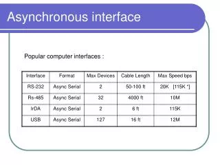
From TTC to TAXI The trigger distribution in the LKr R/O exploits the asynchronusTAXI Chip The RIO-TIC (the Taxi card in the RIOTIC) is equipped with a TAXI-RX (AM7969) linked with the TAXI-TX (AM7968) in the Trigger Supervisor The idea is to exploit the TELL1 (or TEL62) as TTC receiver and to build a daughter board with a TAXI-TX to replace the TS
Trigger toLKr The trigger data arrive in the RIO-TIC with differential PECL signals 48/64 bits serial link from the TS One trigger packet each 100 us with 10 MB/s rate The Serialization , transmission, deserialization and decoding are performed by the same TAXI chip (TX and RX)
Taxi-Tx chip in TS • 12 inputs: • 8 “Dn” not selectable data inputs • 4 “Cn” data or command depending upon the state of DMS pin • DMS at ground means 8 bits wide data bus and 4 bits wide command bus • The clock is supplied by and external crystal oscillator at 10 MHz (should be between 3.3 MHz-17.5 MHz and have to match the TAXI-RX frequency) • Possibility to use an external TTL clksource (JP4A and JP3A) RST (for the internal PPL and logic) and TST not exploited in the TS schematics VCC = +5.0 V , logic “1” for control signals (strobe, ack, rst, …) at VCC The standard FPGAs are LVTTL @3.3 V or LVCMOS (3.3 V): the PP-FPGA (for instance) should control the TAXI chip after a voltage adaptor. The output is a differential PECL pair at 5.0V that, with appropriate pull down resistors, can driving 50 Ohm lines.
Taxi chip in RIOTIC The 10 MHz TTL CLK is provided starting from a crystal oscillator at 20 MHz with a MAX 7000 Altera programmable logic (probably the 20 MHz clock is used also for other purpose) The only external inputs seem to be the SERIALIN (PECL differential pair); apparently the only source of clock is the quartz: probably the TS is also using the quartz and not the external TTL clock (at least for what concerns to the transmission) In our TAXI board the clock should be provided directly through either the PLL in the SL-FPGA (or PP) or a local on board FPGA (present for other purpose).
TAXI board (1) The Taxi board should provide additional inputs and outputs connectors for a better interface with the existing system (XOFF connector, calibration, …) The decoding of the TTCinformations and the preparation of this informations in the TAXI input formats will be done in the SL (or in the PP) The TELL1 will be the TTC receiver, will translate the TTC protocol for the TAXI chip and will be the power supply of the TAXI board: there is still a lot of logic power (5 FPGAs) in the TELL1 for additional features!
TAXI board (2) In the “alpha” run we need a proto-L0TP The Taxi board could be equipped with Ethernet connectors to collect trigger primitives either from other TELL1s or from simple reference counters used for tests The LTU and TTC-ex should be used as TTC signal encoder and transmitter to dispatch trigger decision taken in the TELL1 FPGAs • In order to house the connectors the Taxi board will be 2 Tell1-slots wide • There isn’t a strong reason to build a single double-purpose card (Taxi transmitter and proto-L0TP interface), but : • The FPGA should be directly connected to the TAXI • The ethernet receiver sees 2 PPs (more logic units directly available for multiple algorithms) • The development will be done in parallel, otherwise they are two separated jobs
TAXI board (3) TAXI PECL to RIOTIC XOFF CALIB TELL1 connectors 4xRJ45 FPGA LEMOs LTU connector • FPGA firmware should provide: • Ethernet controller • Direct TAXI controller • Local counter for trigger synchro • Data preparation for LTU
TAXI boardas proto-L0TP STRAWS RICH CHOD LKr SmallScintillator GTK SAC CUSTOM CUSTOM CUSTOM TEL62 TEL62 TEL62 SLM Trigger primit. TELL1+ Taxi Board LTU + TTCex TTC to LTU Trigger to SLM
5 stepsfor the prototype No precise schedule possible at the moment! (prototype ready for the end of next spring???) Help in writing firmware is welcome… Taxi Board design (2 months ???) Taxi Board construction and debug (2 months???) TELL1 FPGA Firmware (2 months???) Taxi Board FPGA Firmware (TAXI control) (1 week???) Taxi Board FPGA Firmware (2 months???)
Conclusions The main purpose of the TAXI board will be to distribute the trigger information coming from the TTC system to the SLM-CPD The TAXI board will house ethernet and “Lemo” receivers The TELL1 with the TAXI board will be used for proto-L0TP, with a small number of channels, to be used in the “alpha” run or in test beams. The TTC signal will be produced with LTU+TTCex: good opportunity to test the entire TDAQ system before the realization of the L0TP We have to design and build the TAXI board and to rewrite the PP (and the SL) Firmware