Download
1 / 13
140 likes | 337 Views
Mini-Project I Touch-sensitive Flasher . Team 3 : Abner Gonzalez , Leader Michael White, Certifier Cameron Wright, Rapporteur. Objectives . •Become familiar with “Electronic Sensor Labs” Kit . • Apply concepts from Learning Styles, Bloom Taxonomy and Knowledge Representation

E N D
Mini-Project I Touch-sensitive Flasher Team 3: Abner Gonzalez , Leader Michael White, Certifier Cameron Wright, Rapporteur
Objectives •Become familiar with “Electronic Sensor Labs” Kit. •Apply concepts from Learning Styles, Bloom Taxonomy and Knowledge Representation •Start building a team (more than a group) •Complete first circuit: touch-sensitive LED flasher
Learning Styles: lessons learned –Understanding types of circuit and wiring diagrams: visual style • Putting the Project Together –Describing components and circuit function: verbal style • Writing the Report/Power Point
Bloom’s Taxonomy & Knowledge Representation: lessons learned –Understanding how the circuit works: cognitive or process of thought –Happy when it works: affective –Implementing the circuit: psychomotor or “skill”
Team building: lessons learned • Leading a team is difficult due to the time schedules of each of the members • We, as a team, gathered on Gmail to collectively write and edit a document • This allowed us to split up the project and view each others work • While working on the project, we learned that each member of our team is quite busy throughout the week, but at the same time we learned how to work around it
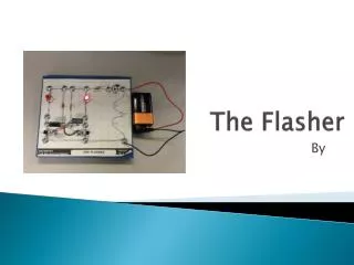
The circuit and components: describe it • Capacitors store an electrical charge. • They block direct current while passing current pulses. • Capacitors in series with resistors are used in circuits that measure time or generate a series of pulses, as in this project. • Resistors resist the flow of electricity. • Very useful for reducing current to LEDs, which can be damaged by to much current. • Most LEDs emit light of one color. • IC • The 8-pin 555 timer IC is used in many projects, a popular version is the NE555. Most circuits will just specify '555 timer IC' and the NE555 is suitable for these. The 555 output (pin 3) can sink and source up to 200mA.
Analysis • The LED flashes due to the current going through the LED causing it to light up, and the 555 prevents flow of current causing an oscillation, which results in the flashes. • In order to find the flashing frequency one must know the time constant of the RC. • In an RC circuit, the value of the time constant (in seconds) is equal to the product of the circuit resistance (in ohms) and the circuit capacitance (in farads). • Then one can use the following formulas: • T=RC • V = Vo(e^-t/RC) • V is the voltage supplied and Vo is the volts that reach the LED.
Analysis • How would one measure the flashing frequency? • A stroboscope, also known as a strobe, is an instrument used to make a cyclically moving object appear to be slow-moving, or stationary. The principle is used for the study of rotating, reciprocating, oscillating or vibrating objects. • In electronic versions, the perforated disc is replaced by a lamp capable of emitting brief and rapid flashes of light. The frequency of the flash is adjusted so that it is an equal to, or a unit fraction below or above the object's cyclic speed, at which point the object is seen to be either stationary or moving backward or forward, depending on the flash frequency.
Analysis • By changing the resistor, one could effectively change the flasher frequency. • A stronger current would in effect, change the flasher brightness.
Testing • The project was tested thoroughly by repeatedly pressing the sensor, causing the LED to flash. • Four individuals verified it worked. • There was a total of two repetitions per individual. • Overall, the team had a total of two failures to make the LED flash. • Once the LED was flashing, every time the sensor was touched the LED lit up, resulting in 100% efficiency.
Conclusions • During this project, we learned how to build an LED mini flasher as a mini-system and to work as a team. We also learned how to problem solve when the circuit would not work at first. We analyzed and tested the system to further understand the circuit and what we were doing. Lastly, we worked as a team to write the report and make a presentation to present our project. • The circuit as a photo-resistor could be used for such things as a street light, clock radio, or alarm.
Work Cited • http://www.kpsec.freeuk.com/components/ic.htm • Mims III, F. M., "Electronic Sensorlab Workbook," RadioShack, Fort Worth, TX.