Download
1 / 32
320 likes | 394 Views
Lab. 1 – Earlier Tasks. Needed by both application and demonstration lab. streams. For more details – see the Lab. 1 web-site There will be a 20 min prelab-quiz (based on Assignment 1 and 2) at the start of the lab. session

E N D
Lab. 1 – Earlier Tasks.Needed by both application and demonstration lab. streams For more details – see the Lab. 1 web-site There will be a 20 min prelab-quiz (based on Assignment 1 and 2) at the start of the lab. session You can make use of YOUR class notes during the prelab-quiz. You CAN’T access the web or use your partner’s notes
Laboratory 1 – Early tasks • Download the C++ Talk-through program. • Check that you can hear the audio output • Convert the ProceessDataCPP( ) code into assembly code ProcessDataASM( ) • Check that you can hear the audio output • Routine for initializing the PF lines (programmable flags) • Use the provided tests to check your code • Develop the ReadProgrammableFlagsASM( ) to read the switches • Use switch information according to laboratory stream requirements
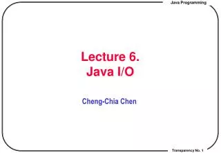
Set up for Tasks 1 and Task 2 AUDIO-IN AUDIO-OUT
Task 1Download audio-talk-through program • If you have not already done so, download and expand ENCM415Directory2006.zip file so that you have the correct directory. structure and test driven development environment needed for Laboratory 1. • Download and expand the files in CPP_Talkthrough.zip into your Lab1 directory. • Add the CPP_Talkthrough project in your Lab. 1 directory to the VisualDSP environment -- compile and link. • Download the executable (.dxe) file onto the BF533 processor. • Hook up your CD or IPOD output to the CJ2 stereo input. • Hook up your ear-phones to the CJ3 stereo output. • Run the CPP_Talkthrough.dxe executable and check that the talk through program is working.
Question What is a “talk-through program”? • Clear example of applying the first two rules of assembly language programming • Rule 1: If you have a choice – don’t use assembly code • It takes as much time (and SOST) to “design, code, review, test and maintain” one line of C++ code as it does assembly code, but one line of C++ often can do more • Rule 2: If somebody has a working example, cannibalize it for your own work (if legal)
The talk through program (C++) Prepare to run C++ code (before you get to main( )) Every1 / 44,000 s Set up the EBIUExternal Bus Unit Store A/D register value(DMA) into memory Use EBIUto initialize A/D and D/A Call ProcessDataCPP( )or ProcessDataASM( ) SET UP theA/D and D/A interrupts Set messages and flagsto main( ) ACTIVATE the A/D and D/A interrupts Load memory (DMA) into D/A register while (1) {/* Wait for messages */ } main( ) ISR -- Interrupt Service Routine
main( ) Prepare to run C++ code(before you get to main( )) int main(void) { sysreg_write(reg_SYSCFG, 0x32); //Initialize System Configuration Register Init_EBIU(); Init_Flash(); Init1836(); Init_Sport0(); // Serial PORT Init_DMA(); Init_Sport_Interrupts(); Enable_DMA_Sport0(); // Serial PORT while (1) { /* */ } } Set up the EBIUExternal Bus Unit Use EBIUto initialize A/D and D/A SET UP theA/D and D/A interrupts ACTIVATE the A/D and D/A interrupts while (1) {/* Wait for messages */ }
ProcessDataCPP( ) #include "Talkthrough.h" extern volatile int iChannel0LeftIn, iChannel0LeftOut; void Process_DataCPP(void) { iChannel0LeftOut = iChannel0LeftIn; iChannel0RightOut = iChannel0RightIn; iChannel1LeftOut = iChannel1LeftIn; iChannel1RightOut = iChannel1RightIn; } TASK 1 – Download the Talkthrough program and check that it works Need an audio in signal (Ipod, CD player)Need ear-phones to check output signal
Task 2 -- ProcessDataASM( ) .extern _iChannel0LeftIn; .section program .global _Process_DataASM__Fv; extern volatile int iChannel0LeftIn, ………….; // #include "Talkthrough.h" // void Process_DataASM(void) // { // iChannel0LeftOut = iChannel0LeftIn; // iChannel0RightOut = iChannel0RightIn; // iChannel1LeftOut = iChannel1LeftIn; // iChannel1RightOut = iChannel1RightIn; // } TASK 2 – Replace ProcessDataCPP( ) by ProcessDataASM( )and check that it works Need an audio in signal (Ipod, CD player)Need ear-phones to check output signal
Task 2 -- Convert ProcessDataCPP( ) to ProcessDataASM ( ) • In talkthrough.h. add a prototype for your assembly code function Process_DataASM; • In ISR.cpp change to // call function that contains user code#if 0 Process_DataCPP(); // Use the C++ version#else Process_DataASM(); // C assembly code routines especially developed for Lab. 1#endif • Right-click on ProcessDataCPP.cpp entry. Use "FILE OPTIONS“ to exclude linking • Use PROJECT | clean project • Add your ProcessDataASM.asm file to the project, recompile and link. Check that your code works • More details on the Lab. 1 web pages
Things to remember • Both MIPS and Blackfin are “RISC” type of processors • They have a “LOAD / STORE” architecture iChannel0LeftOut = iChannel0LeftIn; BECOMES Set P0 to point to address iChannel0LeftIn ?????????Move memory value into registerR0 = [P0]; LOAD Set P1 to point to address iChannel0Out ??????????? Move register value into memory [P1] = R0; STORE REMEMBER – addresses and int, unsigned int valuestogether withlong int, unsigned long int values are 32-bits on this processor
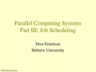
How we are building the volume controller SWITCHES ON FRONT PANEL LED LIGHTS ON FRONT PANEL PROGRAMMABLE FLAGS LED-CONTROLREGISTER FIO_FLAG_D Register EBIU INTERFACE YOUR PROGRAM RUNNING ON THE BLACKFIN int ReadSwitches( ) void WriteLED(int ) ProcessDataASM( ) subroutine IPODCD A/D D/A EARPHONES A/D D/A Interrupt routine
Set-up for Tasks 3 and 4 • De-activate Visual DSP • Power down Blackfin • Connect power to “special Blackfin interface” connector • Connect 50-pin cable to logic-lab • Connect 50-pin cable to Blackfin • Power up logic lab. station • Power up Blackfin • Reactivate Visual DSP • Check that station works using “Lab. 1 test-executable”
Special “power-connector” for Blackfin interface on logic lab. station
Special “power-connector” for Blackfin interface on logic lab. station
Connect 50-pin cable to logic lab • Make sure that all 50-pin connections are secure and proper. • Power up the logic lab. station and check that is working
Task 3 – Initialize the Programmable flag interface – 16 I/O lines on the Blackfin • Warning – could burn out the Blackfin processor if done incorrectly • You need to set (store a known value to) a number of Blackfin internal registers • Most important ones • FIO_DIR – Data DIRection – 0 for input **** • FIO_INEN – INterface ENable – 1 for enabled • FIO_FLAG_D – Programmable FLAGData register
Why do you need to know how to do read (load) and write (store) on internal registers? • Flag Direction register (FIO_DIR) • Used to determine if the PF bit is to be used for input or output -- WARNING SMOKE POSSIBLE ISSUE • Need to set pins PF11 to PF8 for input, leave all other pins unchanged
Making sure that the FIO_DIR is correct for LAB. 1 – NOTE may need to change for later labaoratories Write the Blackfin assembly language instruction(s) to load the address of the internal programmable flag FIO_DIR register into pointer register P1 – then set the Blackfin PF lines to act as inputs
Registers used to control PF pins • Flag Input Enable Register • Only activate the pins you want to use (saves power in telecommunications situation) • Need to activate pins PF11 to PF8 for input, leave all other pins unchanged
Registers used to control PF pins • Flag Data register (FIO_FLAG_D) • Used to read the PF bits (1 or 0) • Need to read pins PF11 to PF8, ignore all other pins values
Task 3 – Setting up the programmable flag interface • Follow the instructions carefully • FIO_DIR – direction register – write 0’s to all bits • In later laboratories will be writing 1’s to some bits and writing 0’s to other bits – DO IT RIGHT • FIO_INEN – input enable register – write 1’s to bits 8, 9, 10, 11 • Other registers set to 0 • There is a test program (Weds lecture) that will enable you to check your code – provide a screen dump of the test result to show it works • Use PRT-SCR button and then paste in .doc file.
Task 4 – Demonstration stream • Final laboratory requirements Wait for button1 (SW1 – PF8) to be pressed and released (ReadButtonASM() ), then play the sound at half-volume. Wait for button2 (SW2 – PF9) to be pressed and released, play the sound at normal volume Each time button3 (SW3 – PF10) is pressed and released, transfer a known value from an array to the LED display (WriteLEDASM( ) ) and check that the expected value is displayed (ReadLEDASM( ) ) Wait for button4 t (SW4 – PF11) o be pressed and released, quit the program (turn off the sound and stop the processor) • Build Initialize_ProgrammableFlagsASM ( ) • Modify main( ) and ProcessDataASM( ) so that button-operation and volume operation works • MUST HAVE 50 pin cable connected between logic board and Blackfin • Logic board power supply must be turned on
Task 4 – Application stream • Final laboratory requirements • SW1 connected to PF8 -- Mute button (This task) • SW2 connected to PF9 -- Gargle button (Task 5) • SW3 connected to PF10 -- Volume up (Task 7) • SW4 connected to PF11 -- Volume down (Task 7) • Build Initialize_ProgrammableFlagsASM ( ) • Modify main( ) and ProcessDataASM( ) so that MUTE-operation works • MUST HAVE 50 pin cable connected between logic board and Blackfin • Logic board power supply must be turned on
How to use int ReadProgrammableFlagsASM( ) int switch_setting = ReadProgrammableFlagsASM( ); (FIO_POLAR register = 0) All switches unpressed Binary Pattern in FIO_FLAG_D register B????0000???????? All switches pressed Binary Pattern in FIO_FLAG_D register B????1111???????? SWITCHES ON FRONT PANEL PROGRAMMABLE FLAGS FIO_FLAG_D Register int ReadSwitches( ) Binary ? Means – we don’t know what the answer is
How to use int ReadProgrammableFlagsASM( ) int switch_setting = ReadProgrammableFlagsASM( ); (FIO_POLAR register = 0) All switches unpressed Binary Pattern in FIO_FLAG_D register BXXXX0000XXXXXXXX All switches pressed Binary Pattern in FIO_FLAG_D register BXXXX1111XXXXXXXX SWITCHES ON FRONT PANEL PROGRAMMABLE FLAGS FIO_FLAG_D Register int ReadSwitches( ) Binary X Means – we don’t know what the answer is – and don’t care
Echoing the switches to the LEDCode in main( ) – written in C++ int main( ) { InitializeSwitchInterface( ); // Check Lab. 1 for “exact name needed” InitializeLEDInterface( ); #define SWITCHBITS 0x0F00 // Looking in MIPs notes about // using a mask and the // AND bit-wise operation // to select “desired bits” while (1) { // Forever loop int switch_value = ReadProgrammableFlagsASM( ); int desired_bits = switch_value & SWITCHBITS; int LED_light_values = desired_bits >> 8; // Bits in wrong position WriteLEDLights(LED_light_values); } }
Practice example -- Rewrite the code so that loop stops if all the switches are pressed at the same time int main( ) { InitializeSwitchInterface( ); // Check Lab. 1 for “exact name needed” InitializeLEDInterface( ); #define SWITCHBITS 0x0F00 // Looking in MIPs notes about MASKS while (1) { // Forever loop int switch_value = ReadProgrammableFlagsASM( ); int desired_bits = switch_value & SWITCHBITS; int LED_light_values = desired_bits >> 8; // Bits in wrong position WriteLEDLights(LED_light_values); } }
Practice example 2 -- Rewrite the code so that (1) loop stops if all the switches are pressed at the same time and (2) if SW1 is pressed then the volatile int mute_on variable is set to 1, otherwise it is set to 0(3) Always show (in the lights) the last value of the switches int main( ) { InitializeSwitchInterface( ); // Check Lab. 1 for “exact name needed” InitializeLEDInterface( ); #define SWITCHBITS 0x0F00 // Looking in MIPs notes about MASKS while (1) { // Forever loop int switch_value = ReadProgrammableFlagsASM( ); int desired_bits = switch_value & SWITCHBITS; int LED_light_values = desired_bits >> 8; // Bits in wrong position WriteLEDLights(LED_light_values); } }
Laboratory 1 – Tasks 1 to 4 in detail • Download the C++ Talk-through program. • Check that you can hear the audio output • Convert the ProceessDataCPP( ) code into assembly code ProcessDataASM( ) • Check that you can hear the audio output • Routine for initializing the PF lines (programmable flags) • Use the provided tests to check your code • Develop the ReadProgrammableFlagsASM( ) to read the switches • Use switch information according to laboratory stream requirements