Download
1 / 24
240 likes | 394 Views
EuCARD-WP7-HFM ESAC Review of the dipole design Engineering Design. Pierre MANIL CEA/iRFU/SIS January 20, 2011 @ Saclay. Contents. Inputs Magnet detailed geometry Overview Ends Layer jump Cable needs Structure detailed geometry Overview Focus Masses Detailed engineering

E N D
EuCARD-WP7-HFMESAC Review of the dipole designEngineering Design Pierre MANIL CEA/iRFU/SIS January 20, 2011 @ Saclay
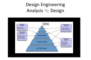
Contents • Inputs • Magnet detailed geometry • Overview • Ends • Layer jump • Cable needs • Structure detailed geometry • Overview • Focus • Masses • Detailed engineering • Materials choice • Tolerances and machining
Inputs • Magnetic inputs[1] • Cable properties • 2D magnetic layout • Mechanical inputs[1] • 2D stress analyze • 3D conceptual study • Constraints [2] • Specified straight section > 700 mm Source: FRESCA2 test station requirements • Overall magnet length = 1500 mm Source: EuCARD contract • Specified aperture = Φ100 mm Source: EuCARD contract • Reaction furnace section = 350 x 200 mm
Magnet detailed geometry • [Draftsman: Jean-François Millot]
Overview • 1.5 m – long • Straight section length > 700 mm ✓ ✓
Preliminary test • HW-bendis OK withthiscable[3] • Ramp angle up to 25° possible • HW ‘safe radius’ ~ 500 mm • Circular end is OK • SeeFrançoise’s talk • Barecoppercable, HFM dimensions • Variable ramp angle • Versatile HW-bendgeometry • 3 options for the end ~R500
Ends • Geometricaldefinition of the ends [2] • R > 500 mm (test) • Lss > 700 mm • Los > 0 • htot < 200 mm • aperture 61 mm α = 17°, R varies R = 700 mm, α varies
Ends details • 17° ramp, R = 700 mm => Los = 24 mm, Lss = 730 mm (layer jump included) • Can becompared to HD2 [4]: 10° ramp, R ~ 350 mm • Slightdifferencesbetween lead/return end
Layer jump • Several options have been considered[5] • ‘HW soft’ is selected 42 42 36 36 42 42 36 36 43 42 36 35 ✓ (flat)
Layer jump details Layer jump 3-4 [CATIA drawing] HW-bend connection (in a plane) to the bottom layer ‘Chicane’ in the top layer (over 28 mm) Straight section (= 700 mm)
Cable needs • ~ 1 km of cable for the dipole • ~ 50 km of strand in one piece 4 pieces of cable
Structure detailed geometry • Shell-based structure principlefrom Berkeley [6] • Additionalcalculations are stillneeded • Connections (out of the structure) to bedesigned • Assemblyprocess in Maria’s talk • [Draftsman: Pascal Labrune]
Overview 70 mm-thickaluminumshell COIL PACK Iron yoke Bladders and shims Coils 100 mm aperture (no bore tube) Axial pre-stress system 1600 mm 2066 mm Materialcolors: CoilSteelAluminumIronTitaniumAluminum-BronzeInsulation(Tooling)
Focus: coil pack Vertical Pad 171 iron laminations: MAGNETIL (LHC iron) 5.8 mm-thick Rails, pole and horseshoespottedwith the coil No bore tube Steel wedges 5 mm-thick steel plates Horizontal Pad in one steelpiece Flexible insulation (~1 mm)
Focus: poles Layer jumptemplate Soft iron pole Titanium pole Groove for midplane shims Axial stop for midplane shim Vertical contact here Contact over 6 mm Longitudinal positioning notch 500 MPa σeqpeak @ 13 T [1]
Focus: yoke Yoke half 250 iron laminations: MAGNETIL (LHC iron) 5.8 mm-thick Longitudinal Weld Rod holes Notches on bothsides for bladderpositionning Pinning holes x3
Focus: axial compression system Coil/Plate contact offset withgrubscrews Hydraulic pre-stress tooling of the SMC system [7] Clearance for key insertion Φ~30 mm aluminum rods Steel end plates (~100 mm) TO BE DIMENSIONNED
Focus: bladders • 14 bladdersallowed [6] • 1.6 m-long (or 2 x 0.8 m-long) • Target pressure ~100 bars Conicallock (700 bars) Removable insertion shim 2 steel sheets (0.3 mm-thick) Laser-weld all along Water arrival
Focus: keys • 6 keys • 1.6 m-long (or 2 x 0.8 m-long) • Versatile thickness (stack of shims) Nominal steel keys ‘sandwich’ (3+3 mm) Round chamfer all along for insertion Pin Stack of shims (0 to 1000 μm) Handling hole
Masses • Magnet ~ 300 kg (copperdensity) • Structure ~ 10 300 kg (withoutmagnet) Potted poles: 519 kg Coil pack: 2 379 kg * SeePhilippe’s talk
Materials choice Peak stress values from Attilio Milanese [1] * = corner value • 2D stresses are supported • 3D stresses to be checked
Tolerances and machining • Mostly conventional shape tolerances • Refined tolerances on key insertion planes and bladder notches • Lamination machining process • Outer shell: • Outer diameter φ1140 mm • Overall length = 1600 mm, can be divided in several parts • Influence of the cylindrical tolerance between shell and yoke? • Can we allow roll welding?
References [1] Fresca2 conceptual design A. Milanese talk given this morning [2] EuCARD-HFM dipole specification and baseline parameters MPWG EuCARD-HFM internal note, January 2011 [3] EuCARD-HFM : Rapport sur les essais de cintrage des têtes de bobine en configuration bloc F.Rondeaux, A. Przybylski, P.Manil CEA report, ref. SAFIRS 00152 A, June 2010 [4] Design of HD2: a 15 Tesla Nb3Sn Dipole with a 35 mm Bore G. Sabbi et al. IEEE Trans. Appl. Supercond., 2005 [5] 21-10-10 - Status of the turns-by-turns model P. Manil, J.-F. Millot EuCARD-HFM internal note, October 2010 [6] The use of pressurized bladders for stress control of superconducting magnets S. Caspi IEEE Trans. Applied Superconductivity, vol. 16, Part 2, pp. 358–361, June 2006 [7] Mechanical Design of the SMC (Short Model Coil) Dipole Magnet F. Regis et al. IEEE Trans. Appl. Supercond., Vol. 20, 2010 [8] NF E 01-000 and NF A 50-451