Download
1 / 40
400 likes | 533 Views
EuCARD -HFM ESAC Review of the high field dipole design Fabrication process study. Maria Durante CEA DSM/IRFU/SACM 20/01/2011 . Outline. Fabrication process : main steps Coil fabrication steps and tooling Coil assembly steps and tooling Magnet assembly steps and tooling Conclusions.

E N D
EuCARD-HFM ESAC Review of the high field dipole designFabrication process study Maria Durante CEA DSM/IRFU/SACM 20/01/2011
Outline • Fabrication process : main steps • Coil fabrication steps and tooling • Coil assembly steps and tooling • Magnet assembly steps and tooling • Conclusions
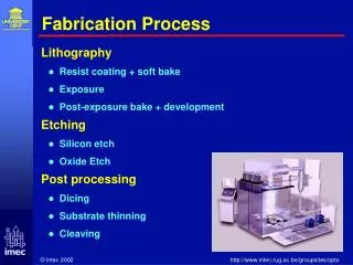
Fabrication process : main steps • Conductor insulation and preparation • Winding • Preparation for the heat treatment • Reaction mold assembly • Heat treatment • Preparation for impregnation : • Nb3Sn/NbTi splice soldering • Instrumentation, ground insulation and quench heaters integration • Impregnation • Coil assembly • Magnet assembly
Conductor insulation • Conductor insulation will rely on a mineral fiber socket • placed around conductor during conductor preparation or • braided around conductor in-line with winding • Conductor insulation will be completed by a vacuum impregnation with resin of each coil • Studies on insulation are carried out by STFC-RAL • Conductor unit length for coil 1 (layers 1-2) : 230 m • Conductor unit length for coil 2 (layers 3-4) : 260 m • Before winding, conductor unit lengths will be split on two different mandrels, one for each coil layer
Winding • Coil Winding will be realized with flared heads upside-down • Preliminary winding tests are foreseen in order to evaluate possible tooling/machine interferences see preliminary tests presentation • Pole pieces will be integrated to the coil from the beginning of the winding. • The pole pieces will be insulated (Al02 coating ?)
Winding • Coil winding will start by forming the layer jump and by positioning it in a groove machined in the pole piece (coil 1 winding is showed). Fixing tools are foreseen. • Then lower layer first turn will be wound, clockwise.
Winding • Once the first conductor turn have be wound, layer jump fixing plate will be removed and replaced by an insulating spacer, blocked by next conductor turn.
Winding positioning tooling • During winding, conductor turns will be guided and maintained in the right position by different positioning tools, fixed in the straight part and in the heads
Winding • At the end of lower layer winding, some special supports will be put in place in order to maintain lower layer conductor during upper layer winding
Winding • An insulating sheet will be placed over the lower layer • The type of insulating sheet has to be decided • The upper layer will be wound over the insulating sheet • The insulating sheet has to be robust and provide a good winding surface for the upper layer
Winding – Preparation for heat treatment • Horse-shoe end spacers will be adapted to coil winding dimensions and pushed in place. • Lateral rails will be positioned on each side of the coil • This rails can be the final ones, positioned at this step and never removed. In this case an insulating sheet will be placed between the rails and the coil or • This rails can be temporary ones, removed after reaction and replaced by the final ones before the impregnation. In this case a protection sheet could be positioned between the rails and the coil
Preparation for heat treatment • Lateral rails will be maintained by plates, screwed into the lower part of the winding/reaction tool. • The upper plate of the reaction mold will be positioned over the coil. Lateral plates will be screwed into the mold upper plate too.
Preparation for heat treatment • The different parts of the reaction mold will be pushed in the nominal position by screws and stirrups. • Nominal dimension for the coil will be defined following ten stack measurement results (see preliminary tests presentation)
Preparation for heat treatment • Following the heat treatment preliminary test results (see preliminary tests presentation) an heat treatment control strategy will be applied on reaction tooling : • Fix the coil tightly in vertical direction in order to limit coil deformation or • Divide winding support and reaction mold upper plate in several parts in order to manage conductor elongation during the heat treatment. For instance we could foresee to fix bended parts of the coil and let straight parts (central straight section and optional straight section in the heads) free to move.
Heat treatment • Heat treatment temperature will be of about 650°C. Heat treatment cycle will be optimized as soon as production strand will be available. • During heat treatment, coil will be submitted to argon flow • A support structure for the Nb3Sn conductor ends of each coil is foreseen • An extra length of Nb3Sn conductor will be left at each end of the coil in order to limit end effects. TIG soldering of the strand ends could be foreseen in order to avoid tin leakage.
Preparation for impregnation • After the heat treatment, the coil will be transferred into an aluminum impregnation mold. • A returning tool for mold transfer is foreseen • During mold transfer operations, Nb3Sn/NbTi splices will be soldered • Coil instrumentation and quench heater will be added at this step (like for SMC racetracks)
Impregnation • Impregnation mold geometry will be similar to reaction mold one. • It will include Nb3Sn/NbTi splice box which will be impregnated with resin with the coil • A releasing coating will be applied on the parts of the mold in contact with resin
Coil pack assembly • Coil pack will be assembled horizontally • Coil pack assembly will be realized on the lower vertical pad, positioned upside-down. • Supporting systems fixed in the stainless steel part of the pad are foreseen.
Coil pack assembly • Instrumented vertical pad insulation will be placed on lower vertical pad
Coil pack assembly • Coil 2 (layers 3-4), upside down, will be placed on vertical pad insulation • A supporting system for the coil is foreseen : it will be fixed on pole piece heads, lateral rails and horse-shoe end spacers. For coil 2 (layers 3-4) it could also be fixed in the straight section of the pole piece.
Coil pack assembly • Coil 1 (layers 1-2) will be positioned, upside-down, on coil 2 • A coil supporting system fixed in pole piece heads, lateral rails and horse-shoe end spacers, is foreseen • Axial and azimuthal positioning of the two coils will be provided by pole pieces • An instrumented insulating sheet will be placed between the two coils
Coil pack assembly • The lower mid-plane insulation will be positioned on coil 1
Coil pack assembly • The two steel mid-plane shims will be positioned on the two sides of coil 1
Coil pack assembly • The two steel end wedges will be positioned on the head of coil 1 • Supporting system are foreseen in the wedges • A plate fixed on the vertical pad will align and maintain axially the wedges • The end wedges could be fixed on lateral rails, horse-shoe wedges and pole piece ends
Coil pack assembly • The upper mid-plane insulation will be positioned on end wedges and mid-plane shims
Coil pack assembly • Coil 1 (layers 1-2) will be positioned on upper mid-plane insulation • Azimutal and axial positioning of the upper pole relative to the lower one will be provided by Ti-alloy pole pieces
Coil pack assembly • Coil 2 (layers 3-4) will be positioned on coil 1 • Axial and azimuthal positioning of the two coils will be provided by pole pieces • An instrumented insulating sheet will be placed between the two coils
Coil pack assembly • The instrumented upper vertical pad insulation will be placed on coil 2
Coil pack assembly • The upper vertical pad will be positioned on insulating sheet
Coil pack assembly • The two horizontal pads will be positioned on the two sides of the coil pack and screwed on lower and upper vertical pads
Magnet assembly • Magnet assembly will be realized vertically • Aluminum outer shell will be positioned on a mounting table • Shell supporting system is foreseen
Magnet assembly • The two iron yoke assembly halves will be placed inside the aluminum outer shell • A yoke supporting system is foreseen
Magnet assembly • 4 bladders will be placed between the two halves of the yoke assembly
Magnet assembly • The bladderswillbeinflated in order to let the place for the coilpack insertion
Magnet assembly • After coil pack insertion, yoke bladders could be removed or kept in place
Magnet assembly • The axial compression system will be mounted at each side of the structure • Grub screws will be placed against coil horse-shoe end spacers
Magnet assembly • The yoke bladders will be inflated again and the coil bladders will be inserted around the coil pack. • The pre-stress in the coils will be provided by bladders inflating and axial compression system tightening.
Magnet assembly • Once the nominal pre-stress reached, the pre-stress keys will be inserted between the coil pack bladders and the bladders deflated • This procedure will be repeated as long as the goal pre-stress has been attained
Magnet assembly • The bladders will then be extracted
Conclusions • The actual status of the fabrication process study has been presented • Fabrication process study will be pursued in parallel with structure and tooling detailed design Thank you for your attention