Download
1 / 41
410 likes | 437 Views
Chapter 2. Network Models. LAYERED TASKS. We use the concept of layers in our daily life. As an example, let us consider two friends who communicate through postal mail. The process of sending a letter to a friend would be complex if there were no services available from the post office.

E N D
LAYERED TASKS • We use the concept of layers in our daily life. As an example, let us consider two friends who communicate through postal mail. The process of sending a letter to a friend would be complex if there were no services available from the post office.
THE OSI MODEL • Established in 1947, the International Standards Organization (ISO) is a multinational body dedicated to worldwide agreement on international standards. An ISO standard that covers all aspects of network communications is the Open Systems Interconnection (OSI) model. It was first introduced in the late 1970s. • Note: • ISO is the organization. • OSI is the model.
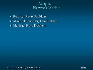
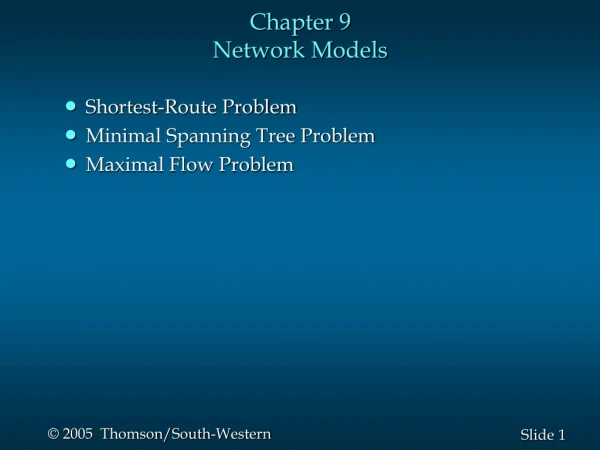
LAYERS IN THE OSI MODEL • Physical Layer • Data Link Layer • Network Layer • Transport Layer • Session Layer • Presentation Layer • Application Layer
Physical Layer • The physical layer is responsible for movements of individual bits from one hop (node) to the next. • Physical characteristics of interface and medium: pin assignment, connector, cables • Representation of bits: encoding • Data rate • Synchronization of bits • Line configuration: point-to-point, multipoint • Physical topology • Transmission mode: simplex, half-duplex, full-duplex
Data Link Layer • The data link layer is responsible for moving frames from one hop (node) to the next. • Framing • Physical addressing • Flow control • Error control • Access control
Network Layer • The network layer is responsible for the delivery of individual packets from the source host to the destination host. • Logical addressing • Routing
Transport layer • The transport layer is responsible for the delivery of a message from one process to another. • Service-point addressing • Segmentation and reassembly • Connection control • Flow control • Error control
Session layer • The session layer is responsible for dialog control and synchronization.
Presentation layer • The presentation layer is responsible for translation, compression, and encryption.
Application layer • The application layer is responsible for providing services to the user.
TCP/IP PROTOCOL SUITE • The layers in the TCP/IP protocol suite do not exactly match those in the OSI model. The original TCP/IP protocol suite was defined as having four layers: host-to-network, internet, transport, and application. However, when TCP/IP is compared to OSI, we can say that the TCP/IP protocol suite is made of five layers: physical, data link, network, transport, and application.
ADDRESSING • Four levels of addresses are used in an internet employing the TCP/IP protocols: • Physical address • Ex. Ehternet address, machine address • Logical address • IP address • Port number • Specific • URL, Email address, domain name
Network layer in TCP/IP • Address resolution • Reverse address resolution • Internet control message • Internet group message
Transport layer in TCP/IP • User Datagram Protocol (UDP) • Connectionless, unreliable • Transmission Control Protocol (TCP) • Connection-oriented, reliable • Stream Control Transmission Protocol (SCTP) • For supporting multimedia and VOIP
Example 2.1 • In Figure 2.19 a node with physical address 10 sends a frame to a node with physical address 87. The two nodes are connected by a link (bus topology LAN). As the figure shows, the computer with physical address 10 is the sender, and the computer with physical address 87 is the receiver.
Physical addresses • The physical addresses will change from hop to hop, • but the logical addresses usually remain the same.
TCP/IP in a Network data data IP (1,2) IP (1,3) data 1,2 data 1,2 1,3 1,3 NI 3487 NI 6537 data 3487 6537 Intro to Computer Communication Networks
Example 2.2 • As we will see in Chapter 13, most local-area networks use a 48-bit (6-byte) physical address written as 12 hexadecimal digits; every byte (2 hexadecimal digits) is separated by a colon, as shown below: • 07:01:02:01:2C:4B
Example 2.3 • Figure 2.20 shows a part of an internet with two routers connecting three LANs. Each device (computer or router) has a pair of addresses (logical and physical) for each connection. In this case, each computer is connected to only one link and therefore has only one pair of addresses. Each router, however, is connected to three networks (only two are shown in the figure). So each router has three pairs of addresses, one for each connection.
data data Router Host B Host A IP (1,2) IP (1,1) (2,3) IP (2,5) data 1,2 data 1,2 data 1,2 2,5 2,5 2,5 NI 3487 NI 6543 NI 1002 NI 3903 data 3487 data 1002 6543 3903 TCP/IP thru a Router Intro to Computer Communication Networks
Example 2.4 • Figure 2.21 shows two computers communicating via the Internet. The sending computer is running three processes at this time with port addresses a, b, and c. The receiving computer is running two processes at this time with port addresses j and k. Process a in the sending computer needs to communicate with process j in the receiving computer. Note that although physical addresses change from hop to hop, logical and port addresses remain the same from the source to destination.
Example 2.5 • As we will see in Chapter 23, a port address is a 16-bit address represented by one decimal number.
Server in TCP/IP • A process waiting a packet on a specific port number • Duplicate a connection after establishing • Connection? • 5 tuple – (PT, SA, SP, DA, DP) • protocol type, source address, source port, destin address, destin port. • A server waits on (pt, sa, sp, any-DA, any-DP) • Upon a request from the client, any-DA and any-DP are filled with specific value. • Server Port Number – 0 to 1023 are reserved to well-known services. Intro to Computer Communication Networks
Berkeley Socket • API – interface available to programmer • socket(), bind(), listen(), accept(), connect(), sendto(), recvfrom(), htonl(), htons(), ntohl(), ntohs() • Utility function - gethostbyname(), gethostbyaddr() • Support multiple communication protocols • Internet Domain • Unix Domain • Xerox NS Domain (XNS) • ATM Domain (Recent progress in several implementation) • References • Richard Stevens, “TCP/IP Programming”, or • http://en.wikipedia.org/wiki/Internet_socket Intro to Computer Communication Networks
Example of Protocol • Interaction between two peer entities • Server/Client • Server – a process waiting a request • Listening a specific port in TCP/IP • Httpd (Apache™) , telnetd, ftpd, … • Client – a process making a request • A request to server address and the port number • Netscape™, telnet, gftp, ws_ftp, … • A connection in a server/client model is a 5-tuple • Protocol type, • Source address, • Destination address • Source port number, • destination port number Intro to Computer Communication Networks
Example of Protocol, http (1) Server Client Listening on port 80 Request to 134.68.80.4:80 Connection established Connection established Send a request GET/index.html HTTP 1.0 Send a result code HTTP/1.1 200 Read and send the file <html> <head> … Interpret and display the html Disconnect the connection time Intro to Computer Communication Networks
TCP and Socket in Client/Server Host B (Server) Host A (Client) socket bind listen socket accept (blocks) connect (blocks) accept (returns) read (blocks) connect returns write read (blocks) read returns write read returns