Download
1 / 51
550 likes | 586 Views
Chapter 2 Network Models. 2.1 LAYERED TASKS. We use the concept of layers in our daily life. As an example, let us consider two friends who communicate through postal mail. The process of sending a letter to a friend would be complex if there were no services available from the post office.

E N D
Chapter 2 Network Models
2.1 LAYERED TASKS We use the concept oflayersin our daily life. As an example, let us consider two friends who communicate through postal mail. The process of sending a letter to a friend would be complex if there were no services available from the post office. Topics discussed in this section: Sender, Receiver, and CarrierHierarchy
Layered Tasks • Sender, Receiver and Carrier
Layered Tasks • Hierarchy • Higher Layer • Middle Layer • Lower Layer • Services • The Each layer uses the services of the layer immediately below it.
2.2 THE OSI MODEL Established in 1947, the International Standards Organization (ISO) is a multinational body dedicated to worldwide agreement on international standards. An ISO standard that covers all aspects of network communications is the Open Systems Interconnection (OSI) model. It was first introduced in the late 1970s. ISO is the organization.OSI is the model. Topics discussed in this section: Layered ArchitecturePeer-to-Peer Processes Encapsulation
Layered Architecture • The OSI model is composed of seven layers ; • Physical (layer1), Data link (layer2), Network (layer3) • Transport (layer4), Session (layer5), Presentation (layer6) • Application (layer7) • Layer • Designer identified which networking functions had related uses and collected those functions into discrete groups that became the layers. • The OSI model allows complete interoperability between otherwise incompatible systems. • The Each layer uses the services of the layer immediately below it.
Layered Architecture (cont’d) Figure 2.2Seven layers of the OSI model
Peer-to-peer Processes • Layer x on one machine communicates with layer x on another machine - called Peer-to-Peer Processes. • Interfaces between Layers • Each interface defines what information and services a layer must provide for the layer above it. • Well defined interfaces and layer functions provide modularity to a network • Organizations of the layers • Network support layers : Layers 1, 2, 3 • User support layer : Layer 5, 6, 7 • It allows interoperability among unrelated software systems • Transport layer (Layer 4) : links the two subgroups
Peer-to-peer Processes (cont’d) Figure 2.3The interaction between layers in the OSI model
Peer-to-peer Processes (cont’d) Figure 2.4An exchange using the OSI model • The data portion of a packet at level N-1 carries the whole packet from level N. – The concept is called encapsulation.
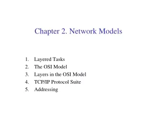
2.3 LAYERS IN THE OSI MODEL In this section we briefly describe the functions of each layer in the OSI model. Topics discussed in this section: Physical LayerData Link Layer Network Layer Transport Layer Session Layer Presentation Layer Application Layer
Physical Layer • Physical layer coordinates the functions required to transmit a bit stream over a physical medium. • The physical layer is responsible for movements of individual bits from one hop (node) to the next.
Physical Layer • Physical layer is concerned with the following: (deal with the mechanical and electrical specification of the primary connections: cable, connector) • Physical characteristics of interfaces and medium • Representation of bits • Data rate : transmission rate • Synchronization of bits • Line configuration • Physical topology • Transmission mode
Data Link Layer • The data link layer is responsible for moving frames from one hop (node) to the next.
Data Link Layer • Major duties • Framing • Physical addressing • Flow control • Error control • Access control
Data Link Layer • Hop-to-hop (node-to-node) delivery
Network Layer • The network layer is responsible for the delivery of individual packets from the source host to the destination host.
Network Layer • Logical addressing • Routing
Transport Layer • The transport layer is responsible for the delivery of a message from one process to another.
Transport Layer Figure 2.11Reliable process-to-process delivery of a message
Transport Layer • Service port addressing • Segmentation and reassembly • Connection control • Flow control • Error control
Session Layer • The session layer is responsible for dialog control and synchronization.
Presentation Layer • The presentation layer is responsible for translation, compression, and encryption
Application Layer • The application layer is responsible for providing services to the user.
Application Layer • The major duties of the application • Network virtual terminal • File transfer, access, and management • Mail services • Directory services
Summary of Layers Figure 2.15Summary of layers
2.4 TCP/IP PROTOCOL SUITE The layers in theTCP/IP protocol suitedo not exactly match those in the OSI model. The original TCP/IP protocol suite was defined as having four layers:host-to-network, internet,transport, andapplication. However, when TCP/IP is compared to OSI, we can say that the TCP/IP protocol suite is made of five layers:physical, data link, network, transport, andapplication. Topics discussed in this section: Physical and Data Link LayersNetwork LayerTransport Layer Application Layer
TCP/IP Protocol Suite Figure 2.16TCP/IP and OSI model
Physical and Data Link Layers • At the physical and data link layers, TCP/IP does not define any specific protocol. • It supports all the standard and proprietary protocols. • A network in a TCP/IP internetwork can be a local-area network or a wide-area network.
Network Layer • TCP/IP supports the Internetworking Protocol. • IP uses four supporting protocols : ARP, RARP, ICMP, and IGMP. • IP (Internetworking Protocol) • ARP (Address Resolution Protocol) • RARP (Reverse Address Resolution Protocol) • ICMP (Internet Control Message Protocol) • IGMP (Internet Group Message Protocol)
Transport Layer • The transport layer was represented in TCP/IP by two protocols : TCP and UDP. • IP is a host-to-host protocol • TCP and UDP are transport level protocols responsible for delivery of a message from a process to another process. • UDP (User Datagram Protocol) • TCP (Transmission Control Protocol) • SCTP (Stream Control Transmission Protocol)
Application Layer • The application layer in TCP/IP is equivalent to the combined session, presentation, and application layers in the OSI model. • Many protocols are defined at this layer.
2-5 ADDRESSING Four levels of addresses are used in an internet employing the TCP/IP protocols:physical,logical,port, andspecific. Topics discussed in this section: Physical AddressesLogical AddressesPort AddressesSpecific Addresses
Addresses Figure 2.17Addresses in TCP/IP
Addresses (cont’d) Figure 2.18Relationship of layers and addresses in TCP/IP
Physical Addresses • The physical address, also known as the link address, is the address of a node as defined by its LAN or WAN. • It is included in the frame used by the data link layer. • The physical addresses have authority over the network (LAN or WAN). • The size and format of these addresses vary depending on the network.
Physical Addresses (cont’d) Example 2.1 In Figure 2.19 a node with physical address 10 sends a frame to a node with physical address 87. The two nodes are connected by a link (bus topology LAN). As the figure shows, the computer with physical address10is the sender, and the computer with physical address87is the receiver.
Physical Addresses (cont’d) Figure 2.19Physical addresses
Physical Addresses (cont’d) Example 2.2 As we will see in Chapter 13, most local-area networks use a48-bit(6-byte) physical address written as 12 hexadecimal digits; every byte (2 hexadecimal digits) is separated by a colon, as shown below: 07:01:02:01:2C:4B A 6-byte (12 hexadecimal digits) physical address.
Logical Addresses • Logical addresses are necessary for universal communications that are independent of underlying physical networks. • Physical addresses are not adequate in an internetwork environment where different networks can have different address formats. • A universal addressing system is needed in which host can be identified uniquely, regardless of the underlying physical network.
Logical Addresses (cont’d) Example 2.3 Figure 2.20 shows a part of an internet with two routers connecting three LANs. Each device (computer or router) has a pair of addresses (logical and physical) for each connection. In this case, each computer is connected to only one link and therefore has only one pair of addresses. Each router, however, is connected to three networks (only two are shown in the figure). So each router has three pairs of addresses, one for each connection.
Logical Addresses (cont’d) Figure 2.20IP addresses The physical addresses will change from hop to hop, but the logical addresses usually remain the same.
Port Addresses • The IP and the physical address are necessary for a quantity of data to travel from a source to the destination host. • The end object of Internet communication is a process communicating with another process. • For these processes to receive data simultaneously, we need a method to label assigned to a process is called a port address. • A port address in TCP/IP is 16 bits in length.
Port Addresses (cont’d) Example 2.4 Figure 2.21 shows two computers communicating via the Internet. The sending computer is running three processes at this time with port addresses a, b, and c. The receiving computer is running two processes at this time with port addresses j and k. Processain the sending computer needs to communicate with processjin the receiving computer. Note that although physical addresses change from hop to hop, logical and port addresses remain the same from the source to destination.
Port Addresses (cont’d) Figure 2.21Port addresses The physical addresses will change from hop to hop, but the logical and port addresses usually remain the same.
Port Addresses (cont’d) Example 2.5 As we will see in Chapter 23, a port address is a 16-bit address represented by one decimal number as shown. 753A 16-bit port address represented as one single number.
Specific Addresses • Some applications have user-friendly addresses that are designed for that specific address. • E-mail address • URL (Universal Resource Locator)
Summary (1) • The International Standards Organization (ISO) created a model called the Open Systems Interconnection, which allows diverse systems to communicate. • The seven-layer OSI model provides guidelines for the development of universally compatible networking protocols. • The physical, data link, and network layers are the network support layers. • The session, presentation, and application layers are the user support layers. • The transport layer links the network support layers and the user support layers. • The physical layer coordinates the functions required to transmit a bit stream over a physical medium. • The data link layer is responsible for delivering data units from one station to the next without errors.
Summary (2) • The network layer is responsible for the source-to-destination delivery of a packet across multiple network links. • The transport layer is responsible for the process-to-process delivery of the entire message. • The session layer establishes, maintains, and synchronizes the interactions between communicating devices. • The presentation layer ensures interoperability between communicating devices through transformation of data into a mutually agreed upon format. • The application layer enables the users to access the network. • TCP/IP is a five-layer hierarchical protocol suite developed before the OSI model. • The TCP/IP application layer is equivalent to the combined session, presentation, and application layers of the OSI model.
Summary (3) • Four levels of addresses are used in an internet following the TCP/IP protocols: physical (link) addresses, logical (IP) addresses, port addresses, and specific addresses. • The physical address, also known as the link address, is the address of a node as defined by its LAN or WAN. • The IP address uniquely defines a host on the Internet. • The port address identifies a process on a host. • A specific address is a user-friendly address.