Download
1 / 6
60 likes | 73 Views
Power Ampliufb01ers for mm-Wave 5G Applications<br>Power Ampliufb01ers for mm-Wave 5G Applications

E N D
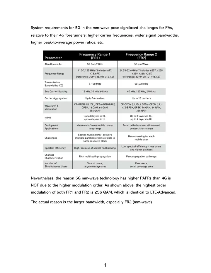
System requirements for 5G in the mm-wave pose significant challenges for PAs, relative to their 4G forerunners: higher carrier frequencies, wider signal bandwidths, higher peak-to-average power ratios, etc.. Nevertheless, the reason 5G mm-wave technology has higher PAPRs than 4G is NOT due to the higher modulation order. As shown above, the highest order modulation of both FR1 and FR2 is 256 QAM, which is identical to LTE-Advanced. The actual reason is the larger bandwidth, especially FR2 (mm-wave). 1 1
The power that must be delivered to each antenna is set by the application. The effective isotropic radiated power (EIRP) requirements are in turn set by the link budget, and differ for applications, such as handset, access point, base station, etc. The link budget calculation is as below [1]: The power per PA, Po, required to feed each antenna to achieve a given EIRP is profoundly affected by the Nant, the number of antennas used. For antenna gain, Gant, (∼5 dB for a representative patch), and loss, Lant, between PA and antenna (∼2 dB to account for the switch and interconnects, potentially much higher in various packagingdesigns). 2 2
According to the formula, if we fix the EIRP, Po is inversely proportional to Nant. That is, more antennas can relax the PA output power requirement. The aggregate power dissipation of the PAs and overall system efficiency is also strongly affected by Nant, since dc power dissipated is minimized when the radiated power is highly directional (i.e., high gain) and focused on the individual receivers. To put it another way, more antennas and higher gain can relax the PA output power requirement and relieve the thermal issue. So, the power requirements for each PA are lower in 5G than for 3G and 4G due to the use of multiple PAs and the improved directionality[1]. 3 3
Additionally, the attainable PAE for the PAs is challenging as a result of wide bandwidth, 800 MHz for base stations, and 200 MHz for handsets. In terms of OFDM, the broader bandwidth brings higher PAPR due to more subcarriers, which poses stricter requirements on linearity. The EVM should be below 5.5% (or -25.2 dBc) to sustain a low bit error rate. And, the ACLR should be at least −25 to −30 dBc. DPD is applied to linearize the PA to correct for AM-AM and AM-PM effects and to increase the efficiency by pushing the compression point to higher output powers. This technique can improve linearity in the linear region (amplitude and phase) [4]. Thus, in 3G and 4G, with lower signal bandwidth and higher output powers, the use of DPD provides an opportunity to achieve high linearity. Nevertheless, in 5G, these requirements above, such as EVM and ACLR, are expected to be met without DPD because of broad bandwidth, which enhances the sample rates of digitization and current consumption dramatically. Also, the linearity of the PAs is profoundly influenced by the bias condition. Practically, you can tune ICQ (Quiescent Current) point to improve ACLR and EVM. 4 4
As mentioned above, 5G has high PAPR due to wide bandwidth, which requires large backoff to sustain linearity. Nevertheless, large backoff results in poor PAE. Consequently, Doherty and outphasing PAs are used to improve efficiency. Outphasing power amplifiers enhance efficiency at lower output power amplitudes by operating the two amplifiers in saturation most of the input signal cycle [5]. The Doherty power amplifier is a form of class B amplifier configuration that achieves high efficiency by having two amplifier sections. One amplifier section caters for the lower amplitude signal situations. A second amplifier is then brought in to use to provide the capability to meet the higher level signals conditions without running into compression [6]. 5 5
Reference [1] Power Amplifiers for mm-Wave 5G Applications: Technology Comparisons and CMOS-SOI Demonstration Circuits [2] Exploring 5G RF Technology [3] Selecting the Right Supplies for Powering 5G Base Stations Components [4] Envelope Tracking and Digital Pre-Distortion Test Solution for RF Amplifiers Application Note [5] Simplified Analysis and Design of Outphasing Transmitters Using Class-E Power Amplifiers [6] What is a Doherty Amplifier 6 6